Datacenter Application Control Engine (ACE) – High Availability
Although Cisco Application Control Engine (ACE) modules are End of Live, it is still common to find them deployed in Datacenters. The intention of this post is to get a better understanding of a High Availability deployment for Routed Mode with some cases of study.
ACE Routed Mode
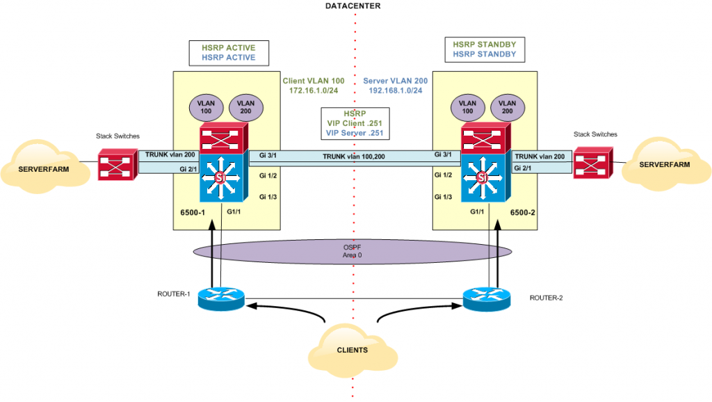
The aim behind this topology is to ensure that traffic in both directions goes through the ACE, client to server and server to client.
The ACE can act as a router between clients and servers, providing a level of protection by effectively hiding the servers from the clients. On the other hand, for a routed topology to work, each of those servers must be configured to route back through the ACE. Figure 1 illustrates the routed mode network topology.
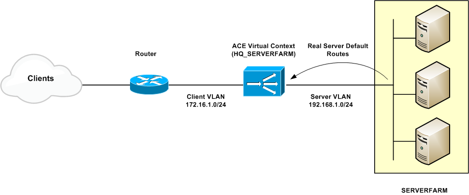
Figure 1
High Availability Design
High Availability (or Fault Tolerance) uses a maximum of two ACE appliances to ensure that the network remains operational even if one of the appliances becomes unresponsive. Redundancy ensures that network services and applications are always available. Redundancy provides seamless switchover of flows in case an ACE appliance becomes unresponsive or a critical host or interface fails.
Redundancy Protocol
A maximum of two ACE appliances (peers) for redundancy. Each peer appliance can contain one or more fault-tolerant (FT) groups. Each FT group consists of two members: one active context and one standby context. An FT group has a unique group ID that needs to be configured.
Each FT group acts as an independent redundancy instance. When a switchover occurs, the active member in the FT group becomes the standby member and the original standby member becomes the active member. A switchover can occur for the following reasons:
- The active member becomes unresponsive.
- A tracked host or interface fails.
- A switchover is forced for a high availability group.
To clients and servers, the active and standby FT group members appear as one node.
The ACE sends and receives all redundancy-related traffic (protocol packets, configuration data, heartbeats, and state replication packets) on a dedicated FT VLAN. This dedicated VLAN cannot be used for normal traffic.
The ACE uses the heartbeat to probe the peer ACE, rather than probe each context. When an ACE does not receive a heartbeat from the peer ACE, all the contexts in the standby state become active.
The election of the active member within each FT group is based on a priority scheme. The member configured with the higher priority is elected as the active member. If a member with a higher priority is found after the other member becomes active, the new member becomes active because it has a higher priority. This behaviour is known as preemption and is enabled by default.
Stateful Failover
The ACE replicates flows on the active FT group member to the standby group member per connection for each context. The replicated flows contain all the flow-state information necessary for the standby member to take over the flow if the active member becomes unresponsive.
For the replication process to function properly and successfully replicate the configuration for a user context when switching from the active context to the standby context, ensure that each user context has been added to the FT group.
The state information passed to the standby appliance includes the following data:
- Network Address Translation (NAT) table based on information synchronized with the connection record.
- All Transmission Control Protocol (TCP) and User Datagram Protocol (UDP) connections not terminated by the ACE appliance.
- HTTP connection states (Optional).
- Sticky table.
In a user context, the ACE appliance allows a switchover only of the FT group that belongs to that context. In the Admin context, the ACE appliance allows a switchover of all FT groups in all configured contexts in the appliance.
Fault-Tolerant VLAN
Redundancy uses a dedicated fault-tolerant VLAN between redundant ACEs to transmit flow-state information and the redundancy heartbeat. This dedicated VLAN is not used for normal network traffic.
This same VLAN must be configured on both peer ACEs. A different IP address within the same subnet must be also configured on each ACE for the fault-tolerant VLAN.
The two redundant ACEs constantly communicate over the fault-tolerant VLAN to determine the operating status of each ACE. The standby member uses the heartbeat packet to monitor the health of the active member. The active member uses the heartbeat packet to monitor the health of the standby member. Communications over the switchover link include the following data:
- Redundancy protocol packets.
- State information replication data.
- Configuration synchronization information.
- Heartbeat packets.
Configuration Synchronization
For redundancy to function properly, both members of a fault-tolerant group must have identical configurations. Both ACE appliances include the same bandwidth software license (2G or 1G) and the same virtual context software license.
The ACE automatically replicates the active configuration on the standby member using a process called configuration synchronization (config sync). Config sync automatically replicates any changes made to the configuration of the active member to the standby member. After the ACE synchronizes the redundancy configuration from the active member to the standby peer, it disables configuration mode on the standby.
High Availability Configuration
Topology
This section describes the relevant configuration to deploy the High Availability (HA) design shown in Figure 2. Notice that this is a possible scenario but not necessarily the recommended implementation.
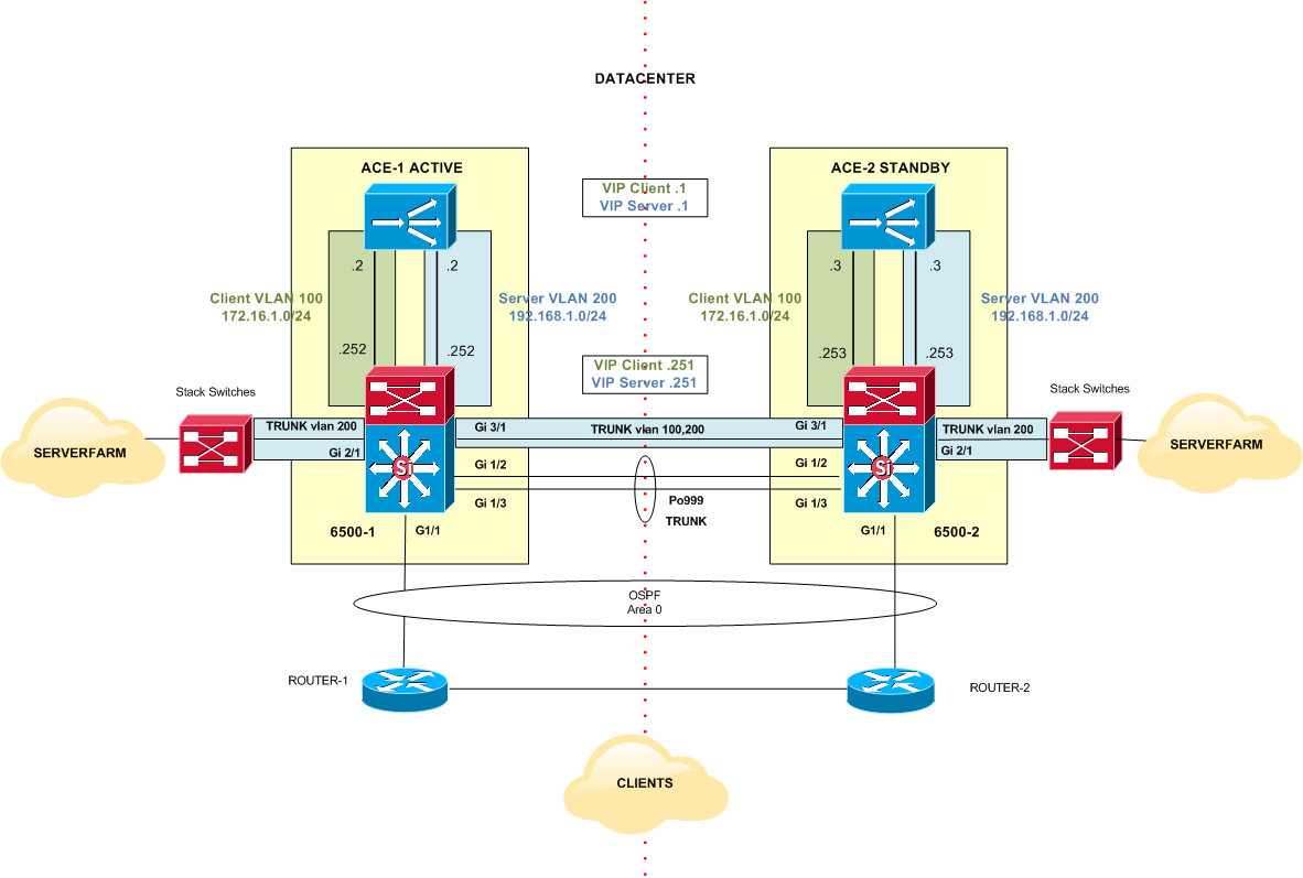
Figure 2
IP Overview
Clients will send application requests through the 6500 Catalyst switches, which route them to a virtual IP address (VIP) within the ACE. The VIP resides in an ACE context, which is configured with a client VLAN (VLAN 100) and a server VLAN (VLAN 200) (Figure 2). Client requests will arrive at the VIP, and the ACE will pick the appropriate server and then use the destination Network Address Translation (NAT) to send the client request to the server. The server will respond using the interface VLAN 200 of the ACE as its default gateway to the client. The ACE will then change the source IP to be the VIP and forward the response to the client via the 6500 Switch.
6500-1
Create and define Client and Server VLANs, VLAN 100 and 200 respectively, and VLAN Interfaces:
interface Vlan200
description *** Server Vlan ***
ip address 192.168.1.252 255.255.255.0
interface Vlan100
description ** Client Vlan **
ip address 172.16.1.252 255.255.255.0
GigabitEthernet2/1 is used to forward traffic from and to the serverfarm.
interface GigabitEthernet2/1
description ** Serverfarm Traffic **
switchport mode trunk
switchport trunk encapsulation dot1q
switchport trunk allowed vlan 200
GigabitEthernet3/1 is used to exchange HSRP keepalives for VLAN 100 and 200 and pass Client requests as it is explained later on in another section.
interface GigabitEthernet3/1
description ***Link to ACE-2***
switchport mode trunk
switchport trunk encapsulation dot1q
switchport trunk allowed vlan 100, 200
6500-2:
Client and Server VLANs and Interface VLANs:
interface Vlan200
description ** Server Vlan **
ip address 192.168.1.253 255.255.255.0
interface Vlan100
description ** Client VLAN **
ip address 172.16.1.253 255.255.255.0
Port configuration for Client, Server and HSRP traffic:
interface GigabitEthernet2/1
description ***Serverfarm Traffic***
switchport mode trunk
switchport trunk encapsulation dot1q
switchport trunk allowed vlan 200
interface GigabitEthernet3/1
description ***Link to ACE-1***
switchport mode trunk
switchport trunk encapsulation dot1q
switchport trunk allowed vlan 100, 200
Client and Server VLAN Interfaces have to be configured in the ACE Context where the serverfarm relevant configuration is defined. In this topology, the context name is HQ_SERVERFARM.
ACE-1- HQ_SERVERFARM Context:
interface vlan 200
description ** Server VLAN **
ip address 192.168.1.2 255.255.255.0
alias 192.168.1.1 255.255.255.0
peer ip address 192.168.1.3 255.255.255.0
no shutdown
interface vlan 100
description ** Client VLAN **
ip address 172.16.1.2 255.255.255.0
alias 172.16.1.1 255.255.255.0
peer ip address 172.16.1.3 255.255.255.0
no shutdown
ACE-2- HQ_SERVERFARM Context:
interface vlan 200
description ** Server VLAN **
ip address 192.168.1.3 255.255.255.0
alias 192.168.1.1 255.255.255.0
peer ip address 192.168.1.2 255.255.255.0
no shutdown
interface vlan 100
description ** Client VLAN **
ip address 172.16.1.3 255.255.255.0
alias 172.16.1.1 255.255.255.0
peer ip address 172.16.1.2 255.255.255.0
no shutdown
Spanning Tree:
The 6500 Catalyst switch that has the Active ACE in the same chassis has to be configured as Root Bridge for Client, Server and FT VLANs. The other 6500 switch can be configured as secondary Root Bridge. This assures Spanning Tree Protocol (STP) does not block unwanted ports and the traffic flow is predictable and efficient.
Therefore 6500-1 is configured as primary Spanning Tree Root Bridge for VLANs 100, 200 and 999 and 6500-2 is configured as secondary Root Bridge for the same VLANs. Lower priority is preferred.
6500-1:
spanning-tree vlan 100,200,999 priority 4096
6500-2:
spanning-tree vlan 100,200,999 priority 8192
HSRP:
In order to get fault tolerant default gateway for Client and Server VLANs, Hot Standby Router Protocol (HSRP) is configured in the topology shown in Figure 2. This allows achieving default gateway failover if the primary gateway becomes inaccessible.
Therefore, it is also important to define the Active HSRP role for Client and Server VLANs on the 6500 switch which has the Active ACE in the same chassis. Under normal situation, the Active HSRP should be 6500-1 which has the Active ACE, ACE-1. This configuration along with the STP configuration and the Active/Standby roles of the ACEs enforces a predictable and efficient traffic path.
6500-1
interface Vlan200
description *** Server Vlan ***
standby 200 ip 192.168.1.251
standby 200 priority 200
standby 200 preempt
standby 200 name HSRP_V200
interface Vlan100
description ** Client Vlan **
standby 100 ip 172.16.1.251
standby 100 priority 200
standby 100 preempt
standby 100 name HSRP_V100
6500-2:
interface Vlan200
description ** Server Vlan **
standby 200 ip 192.168.1.251
standby 200 preempt
standby 200 name HSRP_V200
interface Vlan100
description ** Client VLAN **
ip address 172.16.1.253 255.255.255.0
standby 100 ip 172.16.1.251
standby 100 preempt
standby 100 name HSRP_V100
HA Overview
There are two 6500 Catalyst switches in the Datacenter and each one has an ACE module in slot 2. ACE-1 is the Active peer and ACE-2 is the Standby peer in the HA topology. Both ACEs monitor each other’s heartbeats through the FT VLAN (999) and are able to synchronize configuration from the Active to the Standby.
6500-1
A PortChannel is configured to detect failures in the HA design. FT VLAN is the only VLAN allowed in the trunk:
interface Port-channel999
description *** HEARTBEAT – FT HA ***
switchport mode trunk
switchport trunk encapsulation dot1q
switchport trunk allowed vlan 999
interface GigabitEthernet1/2
description *** FT HA PO999 ***
switchport mode trunk
switchport trunk encapsulation dot1q
switchport trunk allowed vlan 999
channel-group 999 mode desirable
interface GigabitEthernet1/3
description *** FT HA PO999 ***
switchport mode trunk
switchport trunk encapsulation dot1q
switchport trunk allowed vlan 999
channel-group 999 mode desirable
6500-2:
FT PortChannel:
interface Port-channel999
description *** HEARTBEAT – FT HA ***
switchport mode trunk
switchport trunk encapsulation dot1q
switchport trunk allowed vlan 999
interface GigabitEthernet1/2
description *** FT HA PO999 ***
switchport mode trunk
switchport trunk encapsulation dot1q
switchport trunk allowed vlan 999
channel-group 999 mode desirable
interface GigabitEthernet1/3
description *** FT HA PO999 ***
switchport mode trunk
switchport trunk encapsulation dot1q
switchport trunk allowed vlan 999
channel-group 999 mode desirable
In catalyst 6500 supervisor configuration, a vlan-group needs to be configured with the VLANs that are used as CLIENT, SERVER and Fault Tolerant (FT) VLANs for the ACE module in slot 2.
6500-1/6500-2:
svclc multiple-vlan-interfaces
svclc module 2 vlan-group 200
svclc vlan-group 200 100,200,999
There is some HA configuration that needs to be done in ACE modules: a FT interface, a FT peer and a FT group for the context (HQ_SERVERFARM) have to be defined in the Admin context.
ACE-1 (Active) – Admin Context:
ft interface vlan 999
ip address 10.1.1.1 255.255.255.252
peer ip address 10.1.1.2 255.255.255.252
no shutdown
A FT peer configuration mode commands allow configuring redundancy parameters for peer (standby) ACE-2. To configure an alternate interface to allow the standby member to determine whether the active member is down or whether there is a connectivity problem with the fault-tolerant (FT) VLAN, the query-interface command is also configured.
ft peer 1
heartbeat interval 300
heartbeat count 20
ft-interface vlan 999
query-interface vlan 100
context HQ_SERVERFARM
allocate-interface vlan 100,200
member HQ_SERVERFARM
The higher priority value configured in the FT group determines what ACE has the Active role for that context. ACE-1 has a 250 priority value configured versus a 100 (default) priority value in ACE-2. Therefore ACE-1 is Active and ACE-2 is Standby for HQ_SERVERFARM context. Note that by default, preemption is enabled.
ft group 2
peer 1
priority 250
associate-context HQ_SERVERFARM
inservice
FT track host configuration mode commands allow configuring tracking and failure detection for critical network gateways and hosts. FT track HSRP configuration mode allows configuring tracking and failure detection for critical HSRP groups configured on the supervisor engine for the Catalyst 6500 series switch. Two HSRP groups have been defined for tracking Client and Server VLANs, HSRP_V100 and HSRP_V200 respectively, on 6500-1 and 6500-2 switches. “priority 200” represents the decrement value in case of HSRP Tracking failure.
ft track hsrp TRACK_HSRP_V100
track-hsrp HSRP_V100
peer track-hsrp HSRP_V100
priority 200
ft track hsrp TRACK_HSRP_V200
track-hsrp HSRP_V200
peer track-hsrp HSRP_V200
priority 200
ip route 0.0.0.0 0.0.0.0 192.168.1.251
ACE-2 (Standby) – Admin context:
ft peer 1
heartbeat interval 300
heartbeat count 20
ft-interface vlan 999
query-interface vlan 100
context HQ_SERVERFARM
allocate-interface vlan 100,200
member HQ_SERVERFARM
ft group 2
peer 1
peer priority 250
associate-context HQ_SERVERFARM
inservice
ip route 0.0.0.0 0.0.0.0 192.168.1.251
Routing
6500-1 and 6500-2 switches are advertising Client VLAN 100 into OSPF Area 0. Therefore ROUTER-1 and ROUTER-2 prefer the OSPF route through their local Switch, 6500-1 and 6500-2 respectively, to reach VLAN 100 due to lower cost. See Figure 3.

Figure 3
In this specific topology design, ROUTER-1 and ROUTER-2 do not have a second link to the other Switch (6500-1 or 6500-2). This implies the Trunk Link between Switches needs to allow Client and Server VLANs (100 and 200), not only for HSRP to work, to also pass Client and Server traffic.
Because 6500-1 is the HSRP Active in the topology, all Client requests go through this switch. This is the main reason of having the Active ACE (ACE-1) in the same chassis as well as the STP Root Bridge for Client and Server VLANs. It does not make sense to have 6500-1 as Active HSRP and ACE-2 as Active ACE to overcomplicate the design resulting in a more inefficient traffic flow.
If the OSPF cost is not modified, Client requests coming from ROUTER-2 will traverse the Trunk between 6500-1 and 6500-2 in order to reach the Active HSRP (6500-1). 6500-1 passes the Client requests to ACE-1 (Active) which finally send them to the appropriate server according to the predictor mode configured for the Serverfarm. See Figure 4.
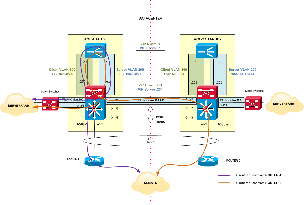
Figure 4
The two clouds of Serverfarms that appear in Figure 4 are not independent entities; they represent the same Serverfarm in the Datacenter that has been previously configured in HQ_SERVERFARM context .
Network with no failures
Figure 5 shows the traffic flow under normal network operation and the HSRP priority values for 6500 switches and ACE modules.
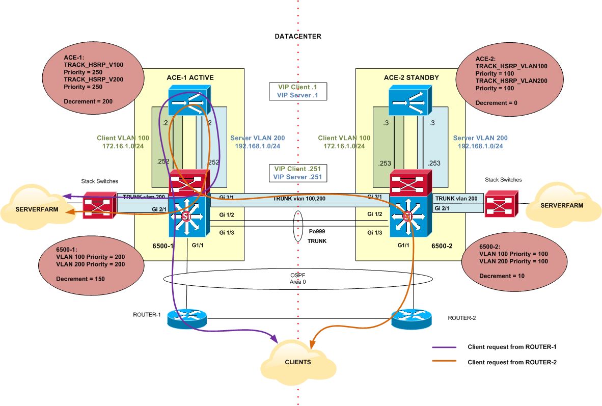
Figure 5
6500-1 priority is 200 for VLAN 100 (Client VLAN) and VLAN 200 (Server VLAN), which are higher than 6500-2 priorities of 100 for VLAN 100 and VLAN 200. Same thing for ACE-1, it has priorities of 250 for both VLANs versus the 100 priorities of ACE-2.
Network with VLAN Failure
Figure 6 shows the scenario where VLAN 100 (Client VLAN) became unavailable in 6500-1 Switch. The following explanation can also be applied to a failure in VLAN 200 in the same Switch.
After a failure, 6500-1 decrements its priority for VLAN 100 to 50 (200-150 decrement = 50). Now, its priority is lower than 6500-2 priority which is 100 for the same VLAN. This causes a HSRP switchover and 6500-2 becomes the Active and 6500-1 becomes the Standby for VLAN 100.
HSRP behaviour is also tracked by the ACEs FT Configuration. ACE-1 detects a switchover of HSRP for VLAN 100 thanks to tracking configuration (ft track hsrp TRACK_HSRP_V100) and decrements its local priority. ACE-1 priority is now 50 (250-200 decrement =50) which is lower than ACE-2 priority 100 for the same VLAN. This causes a switchover and a change of ACE roles.
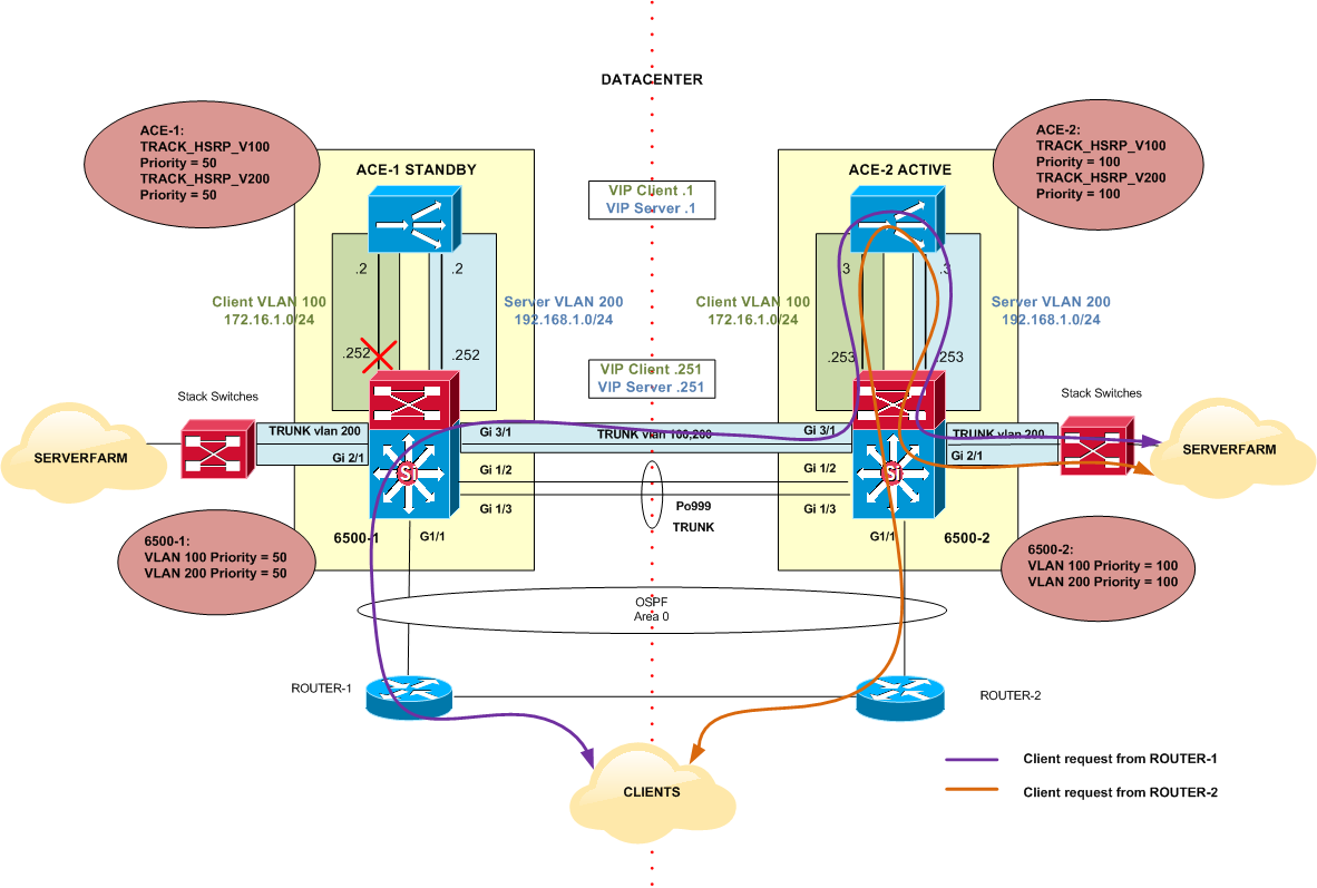
Figure 6
Figure 6 shows the traffic flow after a VLAN failure. As explained before, this switchover is transparent for end users.
Network with Link Failure
However, what would happen if Gi1/1 in 6500-1 switch becomes unavailable with no other failures in the network?
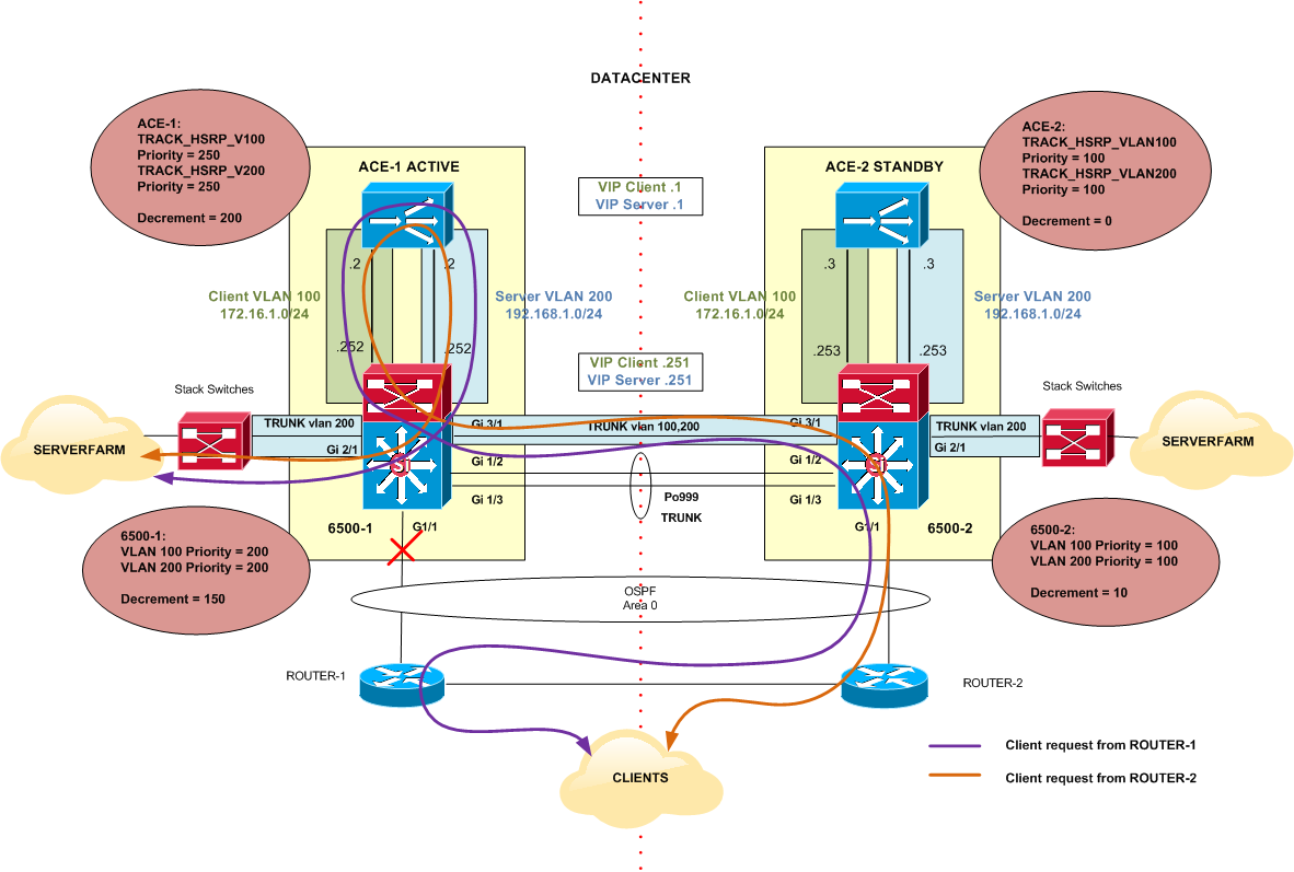
Figure 7
Gi1/1 down on 6500-1 will not cause a switchover of the HSRP roles on the switches. This is because HSRP only monitors VLAN 100 and 200 and there is no tracking for physical interfaces in the configuration. Therefore ACEs will maintain their normal roles too. The whole scenario still works fine, however the traffic flow might not be the most desirable.
It probably makes more sense a switchover to 6500-2 chassis in this situation to avoid extra hops in the network. In order to do that, Gi1/1 can be monitored by HSRP.
6500-1
track 1 interface GigabitEthernet1/1 line-protocol
interface Vlan200
description ** Server Vlan **
standby 200 track 1 decrement 150
interface Vlan100
description ** Client VLAN **
standby 200 track 1 decrement 150
Figure 8 shows the result of the configuration above:
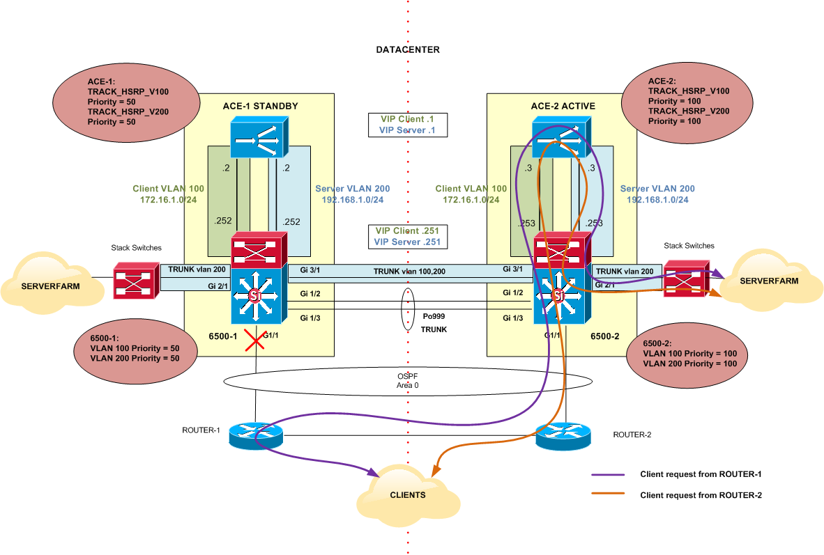
Figure 8
References: