
N+1 HA Wireless LAN Controller
N+1 HA /HA-SKU Wireless Controller Redundancy
The N+1 HA feature builds upon the N+1 redundancy model by allowing a single WLC (Wireless LAN Controller) to be deployed as a backup for multiple primary WLCs. N+1 deployment requires additional AP licenses to be purchased for the backup WLCs which are unused during normal operation.
With an N+1 HA-SKU deployment a WLC is deployed as the backup WLC for multiple primary WLCs without any additional permanent AP licenses being required (see Figure 1).
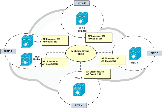
Figure 1
WLC redundancy can be provided within the same site or between geographically separate datacenters. The HA WLC is managed independently and does not share configuration with the primary WLCs. Each WLC needs to be configured and managed separately. The necessary WLANs, AP Groups and RF Groups must be defined on the Backup HA WLC to ensure seamless operation during a failover.
If a primary WLC becomes unreachable or fails, the affected APs (Access Points) failover to the Backup HA WLC. A Backup HA WLC is only licensed to support APs for up to 90-days. As soon as an AP joins the controller a 90-day timer will start. A warning message will be displayed if APs are still present on the Backup HA WLC after the 90-day interval expires. A Backup HA WLC can only be used as a secondary WLC for 90 days without a warning message.
The example shown in Figure 1 demonstrates a N+1 HA deployment for a 1000 AP deployment. Primary WLCs have 250 permanent AP licenses installed. The Backup HA WLC model is selected to initially support 2000 APs and provide room for future growth. APs connected to WLC-1, WLC-2, WLC-3 and WLC-4 are configured to use WLC-BACKUP as their secondary WLC.
Configuration Overview:
Primary and Backup HA-SKU WLCs need to be part of the same Mobility Group. Figure 2 shows the configuration of a Mobility Group named TEST. Each WLC in each site configures itself as part of the Mobility Group in addition to the Backup HA WLC. Therefore in case of a failure, APs will detect their Primary WLC in their site is unavailable and will register with the Backup HA WLC in Site 1.
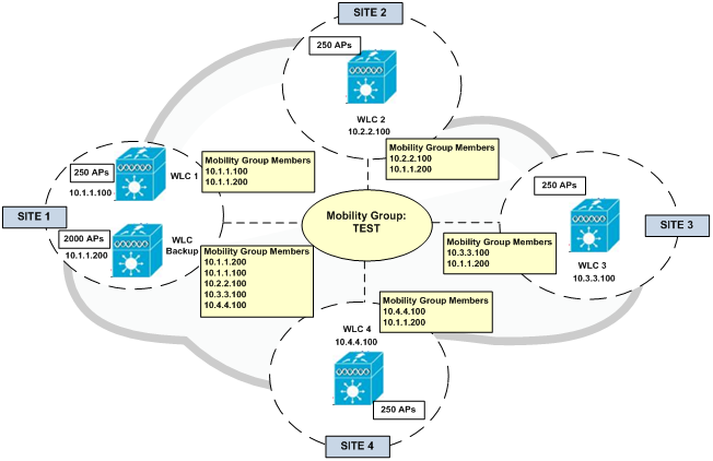
Figure 2
Figure 3 shows an example of the configuration of an AP in Site 2. It has configured its local WLC as Primary and the Backup HA WLC as Secondary. This can be done once the AP registers with its Primary local WLC.
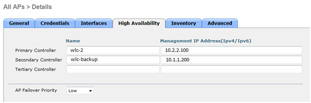
Figure 3
In an event of failure that makes WLC-2 unavailable, APs in Site 2 will failover to WLC-Backup in Site 1. APs still maintain their IP addresses in order to register to the Backup Controller. However, clients are assigned an IP address from the network range configured for the SSID in the Backup Controller. Clients with IP addresses of Site 1 being physically in Site 2 are still able to talk to the network just because their wireless traffic is actually tunnelled to the Backup Controller and transparent to the underlay network (see Figure 4).
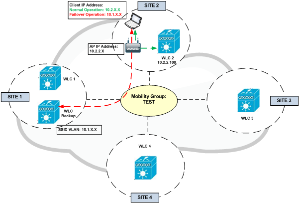
Figure 4
Topology – VSS Distribution Switches
The topology shown in Figure 5 demonstrates a HA-SKU deployment where WLCs are connected to a VSS pair of distribution switches within the wireless services block.
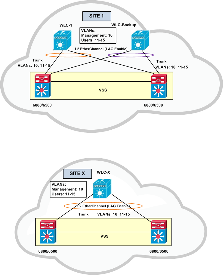
Figure 5
Model Support
HA-SKUs are available for:
- 2500 series
- 5500 series
- 7500 series
- 8500 series
- WiSM2
An N+1 HA deployment can consist of WLCs of different models as primary and WLC HA-SKU backup.
HA Stateful Switchover Wireless Controller Redundancy
As explained before, N+1 HA redundancy architecture provides AP failover in the event that a primary WLC becomes unreachable. This architecture impacts wireless services while APs detect that their primary WLC is unreachable and failover to their secondary. To provide HA without impacting service, there needs to be support for seamless transition of both APs and clients between WLCs. The WLCs implement both AP stateful switchover (AP SSO) and client stateful switchover (Client SSO) to provide zero client service downtime and prevent SSID outages during a WLC failover.
HA stateful switchover (SSO) is the recommended HA deployment architecture for a CUWN (Cisco Unified Wireless Network). This design builds upon the N+1 HA architecture where two WLCs are deployed as a 1:1 primary/secondary pair. The current configuration as well as AP and client state information is automatically synchronized between the primary and secondary peers. For most deployments the primary WLC has the permanent AP licenses installed while the secondary WLC is a HA-SKU (see Figure6).
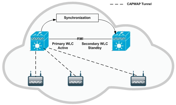
Figure 6
During normal operation the primary WLC assumes an active role while the secondary WLC assumes a standby role. After a switchover, the secondary WLC assumes the active role and the primary WLC assumes the standby role. After subsequent switchovers, the roles are interchanged between the primary and secondary WLCs. The WLCs exchange UDP keep-alive packets through their RMI (Redundancy Management Interfaces) to check peer and management gateway reachability.
Once HA-SSO is enabled all configuration is performed on the active WLC which is automatically synchronized to the standby WLC. No configuration can be performed on the CLI or Web-UI on the standby WLC. Firmware images are also distributed to the standby WLC.
The HA-SSO architecture consists of both AP and client SSO which combine to provide sub-second failure detection and failover without impacting wireless services to clients.
- AP SSO – Allows the APs to establish a CAPWAP tunnel with the active WLC and share a mirror copy of the AP database with the standby WLC. The APs do not go into a CAPWAP discovery state during a failover. There is only one CAPWAP tunnel maintained at a time between the APs and the WLC that is in an active state. The overall goal for AP SSO is to reduce downtime in wireless networks due to failure conditions that may occur such as a WLC or network failover.
- Client SSO – To provide seamless failover without impacting service, there needs to be support for seamless transition of both clients and APs from the active WLC to the standby WLC. With Client SSO, a client’s information is synchronized to the standby WLC when the client associates to the active WLC or the client’s parameters change. All fully authenticated clients are synchronised to the standby WLC and thus, client re-association is avoided during a switch over making the failover seamless for the APs as well as for the clients. This results in zero client service downtime and no SSID outages.
Model Support
AP and client SSO is supported by:
- 5500 series
- 7500 series
- 8500 series
- WiSM2
Each appliance based WLC supports a dedicated redundancy port while the WiSM2 implements a redundancy VLAN. The redundancy port is used to exchange keep-alive messages as well as synchronize configuration and state information. Redundancy ports are either be directly connected or indirectly connected through an intermediate layer 2 network.
Considerations
When implementing HA-SSO, there are some design considerations that should be made. Refer to Enterprise Mobility 8.1 Deployment Guide for further details.
Topology – VSS Distribution Switches
The topology shown in Figure 7 demonstrates a HA-SSO pair of WLCs that are connected to a VSS pair of distribution switches within the wireless services block and is the recommended design. This design minimizes the traffic that crosses the virtual switch link between the Catalyst switches in the VSS pair during normal operation, because both the active and standby WLCs have ports connected to both switches. This design also avoids a switchover from the active WLC to the standby WLC in the event of a switch failure within the VSS pair. However, in the event of a switch failure within the VSS pair, the number of ports connected to the active WLC would be reduced by half.
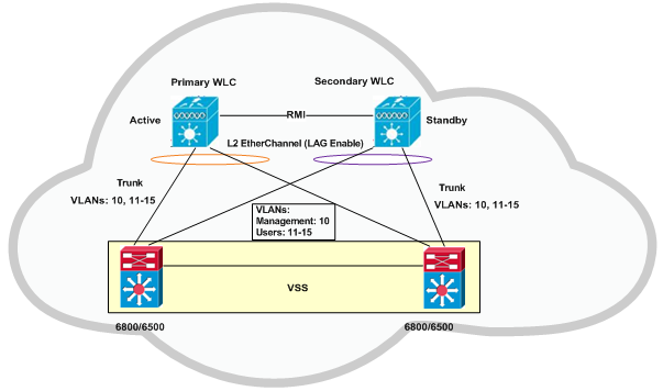
Figure 7
HA-SSO and N+1 Redundancy
For large Cisco Unified Wireless Network (CUWN) deployments both HA-SSO and N+1 redundancy can be combined to provide AP failover in the event that SSO-HA WLCs become unreachable. This is the recommended design for a large CUWN deployment where different HA-SSO pairs are assigned to service APs within a defined geography such as buildings or floors.
The configuration works exactly the same as an N+1 HA deployment where the APs are configured with primary, secondary and tertiary WLCs. The APs primary WLC is configured as their assigned HA-SSO WLC pair, while the secondary (and optionally the tertiary) WLC can be configured as a separate HA-SSO WLC pair or a standalone WLC. The APs will only failover to the secondary WLC if both the active and standby WLCs in the primary HA-SSO pair become unreachable. Failover to the secondary or tertiary WLCs is stateless.
N+1 HA-SKU Summary
- The N+1 HA architecture provides redundancy for controllers across geographically separate datacenters with low cost of deployment.
- A single backup controller can be used in order to provide backup for multiple primary WLCs, with consideration for appropriate compatibility in terms of AP mode.
- These WLCs are independent of each other and do not share configuration or IP addresses on any of their interfaces. Each WLC needs to be managed separately, can run a different hardware and a different software version, and can be deployed in different datacenters across the WAN link.
- When a primary WLC resumes operation, the APs fall back from the backup WLC to the primary WLC automatically if the AP fallback option is enabled.
- When using a permanent AP count license for the backup controller, the 90-day timer does not start when the APs join the backup controller.
- The HA-SKU Unique Device Identifier (UDI) provides the capability of the maximum number of APs supported on that hardware.
- The N+1 Secondary HA-SKU cannot be configured in combination with AP SSO. They are mutually exclusive.
References: