
Network Design Guide
Network design is critical to the success of businesses. Careful planning is the foundation of an efficient, resilient and well-dimensioned network topology able to support business needs.
Content
- Overview
- Design Drivers
- Cost Efficiencies
- Network flexibility and elasticity
- Network resiliency to ensure business continuity
- Standardization and best practice implementations
- Security
- Modularization
- Design Principles
- Failure Domains
- Hiding information
- Hierarchical design networks
- Layer Network Design
- Collapsed Core Network Design
- Layers within Layers Network Design
- Scale up vs. Scale out
- Common Topologies
- Hub and Spoke topology
- Ring topology
- Partial Mesh topology
- Full Mesh topology
- Spine and Leafs
- References
Overview
Networks need to adapt to application and service requirements that are becoming more and more complex. Networks must be available nearly 100 percent of the time, be flexible to support changing traffic loads and be responsive against unexpected security incidents.
Design Drivers
It is important to understand that network design goals are aligned with business strategy. However, the most important factors are usually common to all of them:
Cost efficiency
Network flexibility and elasticity
- Able to change with business needs: Applications and their availability are also ultimate driving factors in network design. Subjects such as bandwidth requirements, best alternative paths for traffic engineering, minimal delay or low jitter ensure a consistent path with no flapping links and faster convergence times. These factors are a must in nowadays networks and it is important to keep in mind that the most critical enterprise application defines the network requirements.
- Responsive to any unexpected events.
- Easy to manage (ideally 0 touch).
Network resiliency to ensure business continuity:
Resilience does not necessarily mean redundant links. More parallel links add resilience however convergence time can go up because the Control Plane needs to work harder for every link added. It is necessary to test the network to understand at what point this happens. Talking in general and as a reference good practices recommend around 2 to 3 parallel links in Core networks and maybe few more in Data Center networks as the Control Plane tends to be simpler.
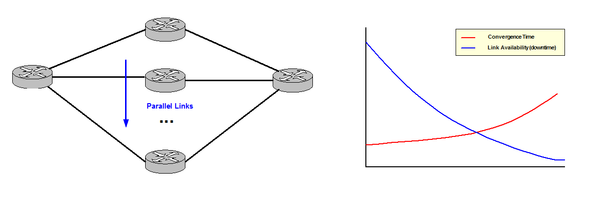
Figure 1
You need to understand the process of convergence after a network failure to comprehend how fast your network is able to recover:
- Discover: How long does it take to discover a failure?
- Protocol Hellos: This is the slowest mechanism as it depends on the Control Plane.
- Bidirectional Forwarding Detection (BFD) Hellos.
- Some kind of courier detection (ASIC): The chipset notifies the protocol process. This is the fastest way for detection of a link down.
- Report: How long does it take to spread the news?
- Calculate: How long does it take to find a new path?
- Install: How long does it take to change to the new path in the local table?
These four steps define the response of your network after a failure.
Standardisation and best practice implementations.
Security:
Security needs to be built in from the beginning in network design.
Nowadays attacks are more sophisticated and firewalls defining an Inside and Outside zones are not enough defenses to protect enterprise networks. Attacks can actually come from the inside of the network.
Therefore a Defense in Depth approach is a much more suitable and effective protection model. The idea behind is to defend a system against any particular attack using several independent methods. It is a layering tactic rather than defeating an attacker with a single, strong defensive line and relies on the tendency of an attack to lose momentum over time. Some examples are patching servers, identifying vulnerabilities, preventing telnet into hosts, etc.
It is also important to define Observation points. They are pre-setup points to monitor what is happening in the network in order to identify abnormal traffic. Consequently we need to clearly define what normal traffic looks like for later comparison.
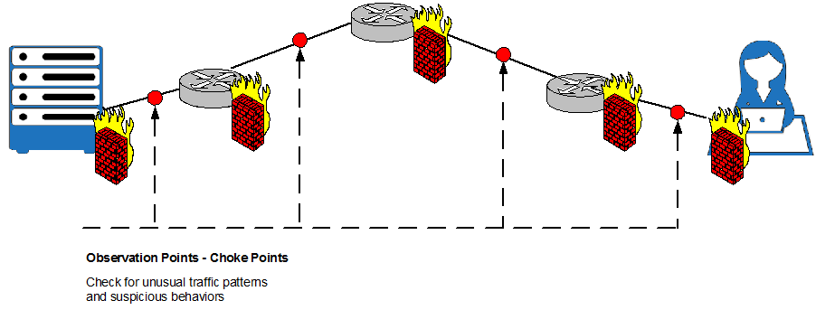
Figure 2
Observation points or Choke Points are critical as it is possible to see attacks as they go through the network, make decisions, prevent leaking and pre-stage policy and specific actions.
OODA Loop Method:
This method is based on the idea of acting faster than attackers can react. OODA Loop is defined by 4 principles:
- Observe what is different in the network as compare to what we define like normal.
- Orient: Understand the final goal of the attacker.
- Decide: Identify decisions to be made before the attack happens. A pre-configured set of steps for possible attacks. This allows making decisions much faster.
- Act: Implement what has been previously decided. Execute and then go back to Observe to verify if the attack has been contained or if it has changed and it is needed to Observe again.
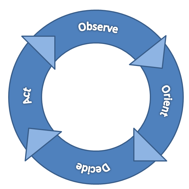
Figure 3
Modularization
Modularization is the first key concept in network design. A module is a component of a composite structure. Modular network design involves creating modules that can then be put together to meet the requirements of the entire network.
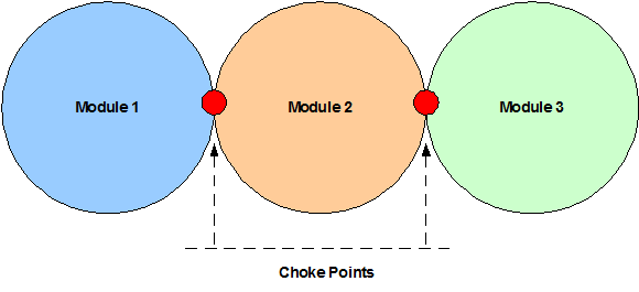
Figure 4
Modules are blocks of different shapes and sizes that contain functionality. Designing one of these blocks is much easier than designing the entire architecture. Each module might be used in multiple places, saving time and effort in the overall design. They can also be removed or replaced independently. Modules also have standard interfaces to each other so that they can talk easily; these are called Choke Points. Modules are independent and any change should be transparent to other modules in the architecture.
Modularity makes easier to break a complex network architecture into smaller pieces easy to understand and define.
Some of the benefits of Modularization are:
- Reduction of the impact of changes.
- Increase resilience through isolation.
- Reduction of processing load within a module.
- Faster and easier troubleshooting improving Mean Time To Repair (MTTR).
- Repeatability of modules reduces operational cost, work building the network and management cost.
- New solutions can easily be placed in the network without impacting other running services. It is possible to test them and test their operation before actually deploy them in production.
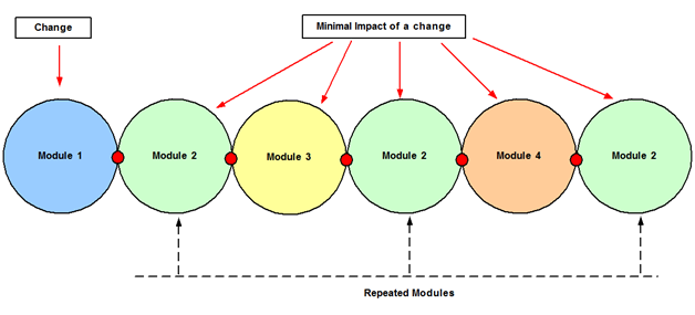
Figure 5
Design Principles
Failure domain:
Failure domain = Broadcast domain; this is a fundamental concept in network design. Large broadcast domains can affect performance and make more difficult to recover after a network change or failure. Broadcast domains need to be well-dimensioned to avoid any impact on the network response time. A Layer 3 switch or a router breaks a broadcast domain; every link is a broadcast segment.
Hiding information:
Hide Information in the Control Plane can help to improve convergence times, reduce the impact of network changes such as a link flapping and increase stability. These are some of the techniques for hiding information in Choke Points:
| Technique | Description | Example |
| Summarization | hides topology information. The router that summarizes advertises the networks as if they were directly connected. The receiver does not have any information about the topology behind. | R2 performs summarization of the more specific prefixes,192.168.1-4.0/24, to the summary 192.168.0.0/21.
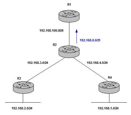 Figure 6 Summarization minimizes the number of routing table entries, localizes impact of a topology change and reduces IGP flooding domain saving CPU resources. 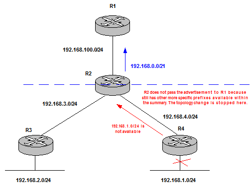 Figure 7 |
| Aggregation | hides reachability information. Normally it also includes Summarization. /23 summary does not advertise /24 networks. However Summarization does not necessarily mean Aggregation because a router can still advertise all the /24 networks as summaries and not summarize to /23 (for a specific network design purpose). | R1 chooses R2 for all destinations. The aggregate prefix from R2 makes R1 to choose a suboptimal path when routing traffic to 192.168.1.0/24.
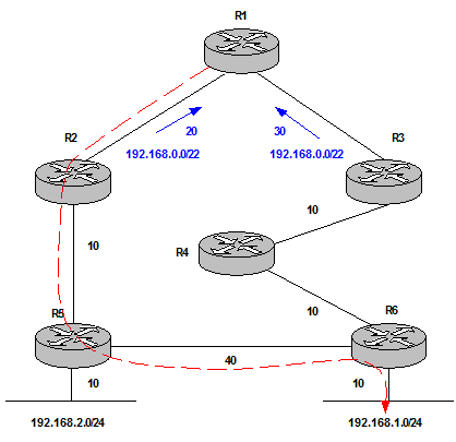 Figure 8 Solution: Leak the more specific prefix in combination with the aggregate. 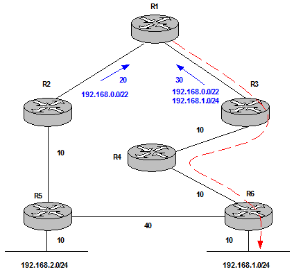 Figure 9 This works fine because we solve the suboptimal routing issue (most specific prefix is always preferred). In addition the aggregate coming from R2 is still installed. Therefore, if there is a network failure between R3 and R4 and 192.168.1.0/24 is not advertised to R1 anymore, R1 still has the aggregate route to reach the destination through R2-R5-R6. The disadvantage is R1 has 3 routes installed in the Routing Table instead of 2 which involves an extra Control Plane load which can or cannot be an issue but it is good to be aware of this. |
| Filtering | blocks prefixes to be advertised to some parts of the network. It is important to keep in mind that black holes can be created. | R1 does not receive any information about the network failure. The change advertisement is stopped by R2 thanks to filtering. This reduces Control Plane operation.
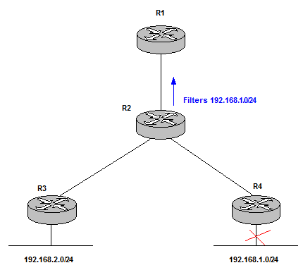 Figure 10 |
| Overlay networks | keep their Control Plane information independent of the underlay Control Plane. This is transparent to the overlay Control Plane. However, failures in underlay networks always have impact on overlay networks (this is called fate sharing). An example is a tunnel; this cannot be formed if the underlay network does not have a route to connect source and destination. | BGP Updates between R1 and R5 does not have any impact on transit routers, R2 and R3. BGP is an overlay method (BGP over IGP). This is called vertical modularity which hides information and builds different failure domains.
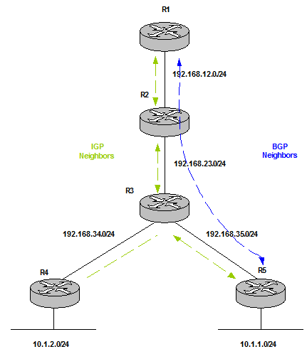 Figure 11 Fate Sharing between BGP and IGP makes the overlay fail (BGP) if the underlay fails (IGP). For example, the link between R2 and R3 goes down. 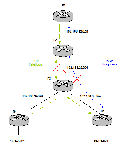 Figure 12 Redundant paths can help to solve this issue. |
| Catching (Reaction) | A router queries for a destination path when a packet is received. It does not know this information in advance; it only asks for it when is needed. |
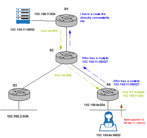 Figure 13 |
Leaky Abstraction is a key concept to be aware of to avoid breaking the whole hidden purpose. Summarization and Aggregation metrics are determined from the more specific prefixes. Therefore, metric changes in the component routes can make the metric of the summary or aggregate prefix to change and also trigger a network update message to advertise it. It is highly recommended to manually configure the metric of a summary or aggregate route.
Modularity, failure domains and resiliency are related to one another. Trying to separate different parts of the network and hide information between them using some of the techniques explained above are considered good practices. The result is each module has its own failure domain and information can be hidden in the Choke Points to avoid further impact on other modules and instability in the network.
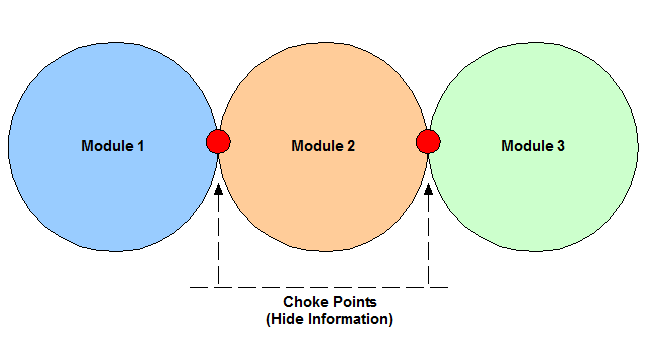
Figure 14
Hierarchical design networks
Figure 15 shows the most traditional 3 Layer Campus Network on the left to more modern networks designs in the centre and on the right.
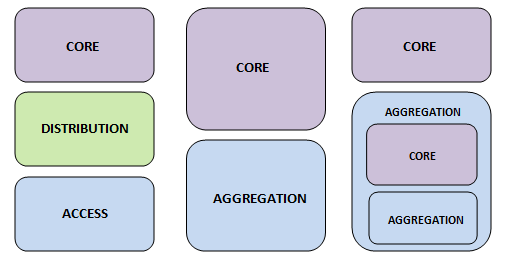
Figure 15
Each module of the hierarchy has its own purpose. This functionality belongs to a module and modules can be placed in the hierarchy where this functionality is needed. These are the different functions that a module can play:
- Forwarding: Carry traffic between modules, areas or regions.
- Aggregation: Combine smaller links into less larger links. Provide redundant links for traffic engineering.
- Policy: Control access, traffic engineering or load balancing.
- Admittance: Attach users and end devices, classify traffic for Quality of Service (Qos), terminate virtual overlays, edge security policies or unicast Reverse Path Forwarding (RPF) filtering.
Layer network design:
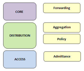
Figure 16
Collapsed Core network design:
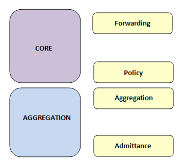
Figure 17
Layers within Layers network design:
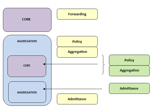
Figure18
Scale up vs. Scale out
This network decision has also a big impact on performance.
Scale up increase the size of an individual component to manage greater levels of traffic and more processing power. On the other hand, Scale out adds more components in parallel.
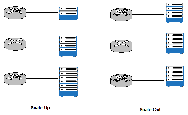
Figure 19
What model is better to chose depends on the type of the workload we are dealing with. Typically Scale out is more efficient and more cost effective. However, the network to connect components needs to be built. In general, Scale out is more matching to network requirements and deployed more often.
Common Topologies
These are some key points which define a network topology:
- Degree of connection: number of alternate paths between two points.
- Regularity and Repeatability: are fundamental factors to predict network behaviour.
- Path Characteristics: bandwidth or delay.
- Convergence Characteristics.
- Troubleshooting Characteristics: how easy is to identify causes of issues in the network.
- Flexibility and Adaptability.
Hub and Spoke topology:
In Hub and Spoke topologies traffic moves along Spokes connected to the Hub at the centre. Spokes‘ traffic never transits other Spokes, traffic always flows through the Hub. Therefore, prefixes are only learnt through the Hub.
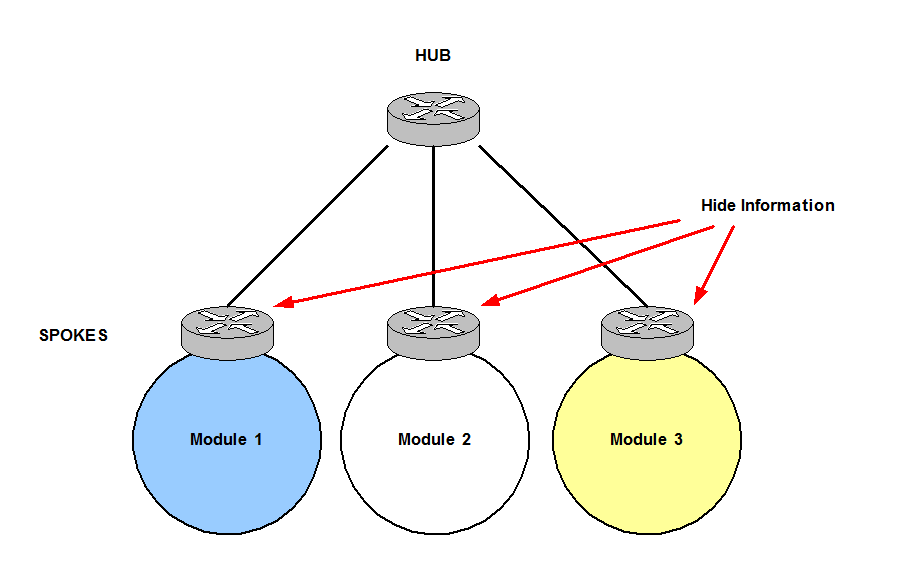
Figure 20
Ring topology:
In Ring topologies, every router has two neighbors and an outage does not cause the network to fail: routers take the other path (direction) available. It is also very easy to add new nodes.
However, it is common to run into very heavy utilization of some links and very underutilize links. Figure 21 shows how the majority of the traffic to the servers on the right is coming from the users on the top, this results in heavy utilization of links A and B whereas the other links of the Ring are underutilized. Some solutions are: using overlay tunnels and configure traffic engineering.
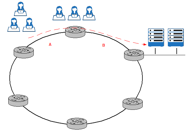
Figure 21
Partial Mesh topology:
It is possible to break Partial Mesh topologies into Hub and Spoke or Ring topologies to understand better how they converge.
Partial Mesh is not a regular topology and non plainer links (overlapping links) make difficult to understand the convergence process.
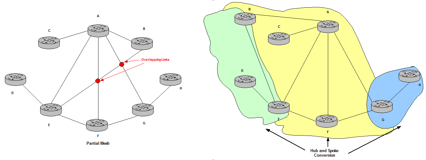
Figure 22
Full Mesh topology:
Full Mesh topologies are called regular non plainer links. They follow a regular design but they have overlapping links. They are also a mix of Ring and Hub and Spoke topologies.
The main issue is the amount of state of routing information. The number of parallel links increases redundancy but also conversion speed. These drawbacks can be solved with Hub and Spoke topologies.
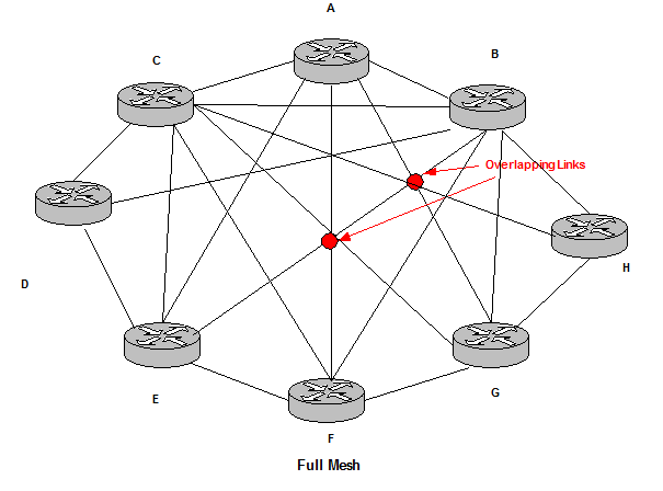
Figure 23
Spine and Leafs:
This topology has become very common in Data Center designs.
It consists in Hub and Spoke networks. Hubs are connected to the same Spokes and this pattern is repeated. It is considered very regular.
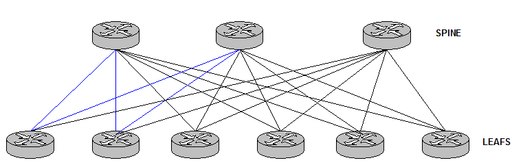
Figure 25
There are no connections between Leaf routers and Spine routers in order to avoid loops. The network design is a bunch of triangles that makes the Control Plane a lot simpler.
References
http://www.ciscopress.com/store/large-scale-network-design-livelessons-best-practices-9780134686523
http://www.cisco.com/c/en/us/td/docs/solutions/Enterprise/Campus/campover.html
http://www.ciscopress.com/articles/article.asp?p=2202410&seqNum=4