
Cisco ASA Cluster – Spanned EtherChannel Mode
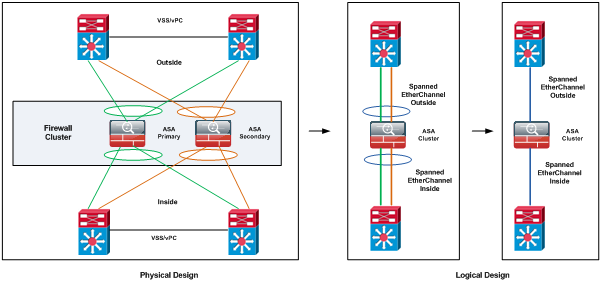
ASA clustering consists of multiple ASAs acting as a single unit, see Figure 1.
Spanned EtherChannel is the Cisco recommended implementation in which interfaces on multiple members of the cluster are grouped into a single EtherChannel; the EtherChannel performs load balancing between units.
When units are combined into a cluster, performance is approximately: 70% of the combined throughput, 60% of maximum connections and 50% of connections per second.
Spanned EtherChannel Benefits
The EtherChannel method of load-balancing is recommended over other methods for the following benefits:
- Faster failure discovery.
- Faster convergence time. Individual interfaces rely on routing protocols to load-balance traffic, and routing protocols often have slow convergence during a link failure.
- Ease of configuration.
Cluster Members:
There is a primary unit (determined by the priority set between 1 and 100, where 1 is the highest priority) and one or multiple secondary units. All units in the cluster share a single configuration and changes can only be made on the primary unit, then they are automatically synced to all other units in the cluster.
Spanned EtherChannel
One or more interfaces per chassis are grouped into an EtherChannel that spans all chassis in the cluster. The EtherChannel aggregates the traffic across all the available active interfaces in the channel. A Spanned EtherChannel can be configured in both routed and transparent firewall modes.
Cluster Control Link
Each unit must dedicate at least one hardware interface as the cluster control link. Cluster control link traffic includes both control and data traffic: Primary election, Configuration replication, Health monitoring, State replication and Connection ownership queries and data packet forwarding.
If possible, the cluster control link should be sized to match the expected throughput of each chassis so the cluster-control link can handle the worst-case scenarios. A higher-bandwidth cluster control link helps the cluster to converge faster when there are membership changes and prevents throughput bottlenecks.
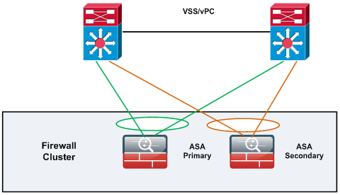
Cisco recommends using an EtherChannel for the cluster control link, so that traffic can pass on multiple links in the EtherChannel while still achieving redundancy. Figure 2 shows how to use an EtherChannel as a cluster control link in a Virtual Switching System (VSS) or Virtual Port Channel (vPC) environment. All links in the EtherChannel are active. When the switch is part of a VSS or vPC, then you can connect ASA interfaces within the same EtherChannel to separate switches in the VSS or vPC. The switch interfaces are members of the same EtherChannel port-channel interface, because the separate switches act like a single switch. Note that this EtherChannel is device-local, not a Spanned EtherChannel.
To ensure cluster control link functionality, the round-trip time (RTT) between units needs to be less than 20 ms. This maximum latency enhances compatibility with cluster members installed at different geographical sites. To check latency a ping on the cluster control link between units can be used. The cluster control link must be reliable, with no out-of-order or dropped packets.
Health Monitoring
The primary unit monitors every secondary unit by sending keepalive messages over the cluster control link periodically. Each secondary unit monitors the primary unit using the same mechanism. If the unit health check fails, the unit is removed from the cluster.
Status after Failure
When a unit in the cluster fails, the connections hosted by that unit are seamlessly transferred to other units; state information for traffic flows is shared over the control cluster link. If the primary unit fails, then another member of the cluster with the highest priority becomes the primary.
The ASA automatically tries to rejoin the cluster, depending on the failure event.
Every connection has one owner and at least one backup owner in the cluster. The backup owner does not take over the connection in the event of a failure; instead, it stores TCP/UDP state information, so that the connection can be seamlessly transferred to a new owner in case of a failure.
If the owner becomes unavailable, the first unit to receive packets from the connection (based on load balancing) contacts the backup owner for the relevant state information so it can become the new owner.
Load Balancing Methods
To achieve maximum throughput, Cisco recommends the following methods:
- Load balancing hash algorithm that is “symmetric”, meaning that packets from both directions will have the same hash, and will be sent to the same ASA in the Spanned EtherChannel. Using the source and destination IP address (the default) or the source and destination port as the hashing algorithm is recommended.
- Use the same type of line cards when connecting the ASAs to the switch so that hashing algorithms applied to all packets are the same.
It is worth notice that the number of links in the EtherChannel affects load balancing.
Symmetric load balancing is not always possible. If you configure NAT, then forward and return packets will have different IP addresses and/or ports. Return traffic will be sent to a different unit based on the hash, and the cluster will have to redirect most returning traffic to the correct unit. I will talk about this in a following section.
Connecting to a VSS or vPC
You can include multiple interfaces per ASA in the Spanned EtherChannel. Multiple interfaces per ASA are especially useful for connecting to both switches in a VSS or vPC.
Figure 3 shows a traditional 8 active/8 standby link spanned EtherChannel in a 4-ASA cluster and an 8-ASA cluster. The active links are shown as green solid lines, while the inactive links are green dotted. cLACP (cluster Link Aggregation Control Protocol ) load-balancing can automatically choose the best 8 links to be active in the Spanned EtherChannel.
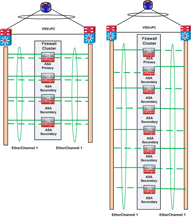
If more than 8 active links are required in a spanned EtherChannel , cLACP dynamic port priority needs to be disable to allow the use of standby links.
How the ASA Cluster Manages Connections
Connection Roles
There are 3 different ASA roles defined for each connection:
- Owner—The unit that initially receives the connection. The owner maintains the TCP state and processes packets. A connection has only one owner.
- Director—The unit that handles owner lookup requests from forwarders and also maintains the connection state to serve as a backup if the owner fails. When the owner receives a new connection, it chooses a director based on a hash of the source/destination IP address and TCP ports, and sends a message to the director to register the new connection. If packets arrive at any unit other than the owner, the unit queries the director about which unit is the owner so it can forward the packets. A connection has only one director.
- Forwarder—A unit that forwards packets to the owner. If a forwarder receives a packet for a connection it does not own, it queries the director for the owner, and then establishes a flow to the owner for any other packets it receives for this connection. The director can also be a forwarder. Note that if a forwarder receives the SYN-ACK packet, it can derive the owner directly from a SYN cookie in the packet, so it does not need to query the director. (If you disable TCP sequence randomization, the SYN cookie is not used; a query to the director is required.) For short-lived flows such as DNS and ICMP, instead of querying, the forwarder immediately sends the packet to the director, which then sends them to the owner. A connection can have multiple forwarders; the most efficient throughput is achieved by a good load-balancing method where there are no forwarders and all packets of a connection are received by the owner.
Sample Data Flow
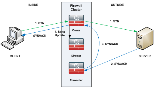
- The SYN packet originates from the client and is delivered to one ASA (based on the load balancing method), which becomes the owner. The owner creates a flow, encodes owner information into a SYN cookie, and forwards the packet to the server.
- The SYN-ACK packet originates from the server and is delivered to a different ASA (based on the load balancing method). This ASA is the forwarder.
- Because the forwarder does not own the connection, it decodes owner information from the SYN cookie, creates a forwarding flow to the owner, and forwards the SYN-ACK to the owner.
- The owner sends a state update to the director, and forwards the SYN-ACK to the client.
- The director receives the state update from the owner, creates a flow to the owner, and records the TCP state information as well as the owner. The director acts as the backup owner for the connection.
- Any subsequent packets delivered to the forwarder will be forwarded to the owner.
- If packets are delivered to any additional units, it will query the director for the owner and establish a flow.
- Any state change for the flow results in a state update from the owner to the director.
When a connection uses Port Address Translation (PAT), then the PAT type (per-session or multi-session) influences which member of the cluster becomes the owner of a new connection:
- Per-session PAT — The owner is the unit that receives the initial packet in the connection. By default, TCP and DNS UDP traffic use per-session PAT.
- Multi-session PAT — The owner is always the primary unit. If a multi-session AT connection is initially received by a secondary unit, then the secondary unit forwards the connection to the primary unit. By default, UDP (except for DNS UDP) and ICMP traffic use multi-session PAT, so these connections are always owned by the primary unit. You can change the per-session PAT defaults for TCP and UDP. However, for ICMP you cannot change from the default multi-session PAT.
Unsupported Features with Clustering
These features cannot be configured with clustering enabled:
- Unified Communication features that rely on TLS Proxy
- Remote access VPN (SSL VPN and IPsec VPN)
- The following application inspections:
- CTIQBE
- H323, H225, and RAS
- IPsec passthrough
- MGCP
- MMP
- RTSP
- SCCP (Skinny)
- WAAS
- WCCP
- Botnet Traffic Filter
- Auto Update Server
- DHCP client, server, and proxy. DHCP relay is supported.
- VPN load balancing
- Failover
- ASA CX module
NAT and Clustering
NAT can impact the overall throughput of the cluster. Inbound and outbound NAT packets can be sent to different ASA in the cluster because the load balancing algorithm relies on IP addresses and ports, and NAT causes inbound and outbound packets to have different IP addresses and/or ports. When a packet arrives at the ASA that is not the connection owner, it is forwarded over the cluster control link to the owner, causing large amounts of traffic on the cluster control link.
If NAT is still used in clustering, then some considerations can be taken:
- No Proxy ARP – For Individual interfaces, a proxy ARP reply is never sent for mapped addresses. The upstream router needs a static route or PBR with Object Tracking for the mapped addresses that points to the Main cluster IP address. This is not an issue for a Spanned EtherChannel, because there is only one IP address associated with the cluster interface.
- No interface PAT on an Individual interface.
- NAT pool address distribution for dynamic PAT — The primary unit evenly pre-distributes addresses across the cluster. If a member receives a connection and they have no addresses left, the connection is dropped, even if other members still have addresses available. Make sure to include at least as many NAT addresses as there are units in the cluster to ensure that each unit receives an address.
- No round-robin—Round-robin for a PAT pool is not supported with clustering.
- Dynamic NAT xlates managed by the primary unit — The primary unit maintains and replicates the xlate table to secondary units. When a secondary unit receives a connection that requires dynamic NAT, and the xlate is not in the table, it requests the xlate from the primary unit. The secondary unit owns the connection.
- Per-session PAT feature — Although not exclusive to clustering, the per-session PAT feature improves the scalability of PAT and, for clustering, allows each secondary unit to own PAT connections; by contrast, multi-session PAT connections have to be forwarded to and owned by the primary unit.
- No static PAT for the following inspections — FTP, PPTP, RSH, SQLNET, TFTP, XDMCP and SIP.
VPN and Clustering
Site-to-site VPN is a centralized feature; only the primary unit supports VPN connections. Remote access VPN is not supported with clustering. VPN functionality is limited to the primary unit and does not take advantage of the cluster high availability capabilities.
If the primary unit fails, all existing VPN connections are lost, and VPN users will see a disruption in service. When a new primary is elected, you must re-establish the VPN connections.
When a VPN tunnel is connected to a Spanned EtherChannel address, connections are automatically forwarded to the primary unit. For connections to an Individual interface when using PBR or ECMP, must always connect to the Main cluster IP address, not a Local address. VPN-related keys and certificates are replicated to all units.
Models Supported on:
- ASA 5585-X
- ASA 5516-X
- ASA 5512-X, ASA 5515-X, ASA 5525-X, ASA 5545-X, and ASA 5555-X
Summary
The most likely deployment scenario for an ASA cluster is in a Datacenter due to the Clustering limitations.
Benefits:
- Active/Active Datacenter designs.
- Faster failure discovery.
- Faster convergence time.
- Ease of configuration.
- Scale throughput.
Limitations:
- No Remote Access VPN support.
- Limited Protocol Inspection.
- NAT Limitations.
References: