Multicast – Inter AS Multicast (Auto-RP and BSR), Anycast RP MSDP, MSDP SA Filter and MBGP
If you want to learn how multicast works and different multicast protocols, you need to read this post. It will guide you through the details progressively to fully understand the key concepts.
Contents
- AS65001 Physical Topology
- AS65001 Multicast Topology – Auto RP
- User 1 Joins 224.1.1.1
- Server1 sends Multicast Traffic to 224.1.1.1
- Building the Shortest-Path Tree (SPT)
- Designated Router (DR) Election
- PIM Assert Mechanism – Forwarder Election
- AS65002 Physical Topology
- AS65002 Multicast Topology – Bootstrap router (BSR)
- User 2 Joins 234.2.2.2
- Server2 sends Multicast Traffic to 234.2.2.2
- Building the Shortest-Path Tree (SPT)
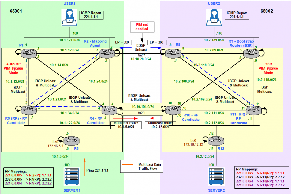
- Merge AS65001 and AS65002 – Physical Topology
- Merge AS65001 and AS65002 – Multicast Topology
- Anycast and Multicast Source Discovery Protocol (MSDP)
- Configuration Requirements
- Server1 sends Multicast Traffic to 224.1.1.1
- Enable Multicast BGP (MBGP)
- Server2 sends Multicast Traffic to 234.2.2.2
- Server 1 and Server2 send Multicast Traffic to 227.3.3.3 – MSDP SA Filtering
- Appendix
- Filter RP-Group in the Mapping Agent
- Filter RP Announcements and Mappings to leave the AS
- ip pim accept-register (S,G)
- ip pim accept-rp (*,G)
- Multicast Stub Routing
AS65001 Physical Topology
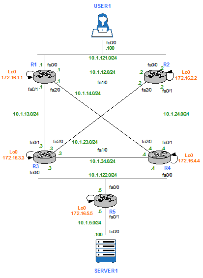
Figure 1
AS65001 Multicast Topology – Auto RP
AS 65001 is running Protocol Independent Multicast (PIM) Sparse Mode (SM) on all links. PIM SM uses explicit Join/Prune Messages and Rendezvous Points (RPs) instead of Dense Mode (DM) broadcast and prune technique.
Cisco proprietary protocol Auto-RP is enabled to dynamically distribute RP information to other routers in the PIM SM domain. As it is shown in Figure 2, R3 an R4 are the candidate RPs and R2 is the Mapping Agent.
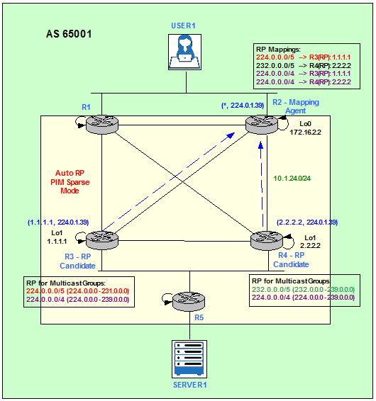
Figure 2
Auto-RP uses two Multicast Groups: 224.0.1.39 and 224.0.1.40. Candidate RPs send RP Announce messages on the 224.0.1.39 Group. These messages contain a list of Multicast Groups the device would like to be the RP for. Mapping Agents listen to 224.0.1.39 in order to collect the RP information from all candidate RPs and send RP Discovery Messages on the 224.0.1.40 Group. The RP Discovery Messages destined to 224.0.1.40 contain the best elected RP-to-Group mapping information from Mapping Agents. All the PIM routers join the Multicast Group 224.0.1.40 when the first PIM-enabled interface comes up.
By default, the RP Discovery Message could not be sent out of PIM SM enabled interfaces. One of the possible solutions to send this information to other PIM Enabled Routers is to enter the ip pim autorp listener command. This causes the IP Multicast traffic for the two Auto-RP Groups, 224.0.1.39 and 224.0.1.40, to be PIM DM flooded across the interfaces configured for PIM SM. This way the routers which listen for Group 224.0.1.40 learn the Auto-RP information and hence learn the RP address.
We enable ip pim autorp listener feature and ip multicast-routing in configuration mode on all routers and ip pim sparse-mode at interface level on all routers’ interfaces.
R1 – R5:
R#conf t
R(config)#ip pim autorp listener
R(config)#ip multicast-routing
R(config)#interface FastEthernet X/Y
R(config-if)#ip pim sparse-mode
R(config)#ip pim autorp listener
R(config)#ip multicast-routing
R(config)#interface FastEthernet X/Y
R(config-if)#ip pim sparse-mode
R3 is the RP for 224.0.0.0/5 (224.0.0.0 – 231.0.0.0) and the whole Multicast range 224.0.0.0/4.
R3(config)#ip access-list standard MULTICAST_GROUPS
R3(config-std-nacl)#permit 224.0.0.0 7.255.255.255
R3(config-std-nacl)#permit 224.0.0.0 15.255.255.255
R3(config-std-nacl)#permit 224.0.0.0 7.255.255.255
R3(config-std-nacl)#permit 224.0.0.0 15.255.255.255
R3(config)# interface Loopback1
R3(config)# ip address 1.1.1.1 255.255.255.255
R3(config-if)# ip pim sparse-mode
R3(config)#ip pim send-rp-announce lo1 scope 100 group-list MULTICAST_GROUPS
R4 is the RP for 232.0.0.0/5 (232.0.0.0 – 239.0.0.0) and the whole Multicast range 224.0.0.0/4.
R4(config)#ip access-list standard MULTICAST_GROUPS
R4(config-std-nacl)#permit 234.0.0.0 7.255.255.255
R4(config-std-nacl)#permit 224.0.0.0 15.255.255.255
R4(config-std-nacl)#permit 234.0.0.0 7.255.255.255
R4(config-std-nacl)#permit 224.0.0.0 15.255.255.255
R4(config)# interface Loopback1
R4(config)# ip address 2.2.2.2 255.255.255.255
R4(config-if)# ip pim sparse-mode
R4(config)#ip pim send-rp-announce lo1 scope 100 group-list MULTICAST_GROUPS
R2 is the Mapping Agent (MA) and receives the Multicast Groups-RP mappings from R3 and R4. Then, R2 selects and advertises only one RP for Multicast Group (in case it receives multiple advertisements from different RPs for the same Multicast Group) to all routers in the Multicast domain.
R2(config)# interface Loopback0
R2(config)# ip address 172.16.2.2 255.255.255.255
R2(config-if)# ip pim sparse-mode
R2(config)# ip address 172.16.2.2 255.255.255.255
R2(config-if)# ip pim sparse-mode
R2(config)# ip pim send-rp-discovery lo0 scope 100
Figure 3 shows the Auto-RP discovery process. R2 receives two possible mappings for 224.0.0.0/4: 224.0.0.0/4 – 1.1.1.1 from R3 and 224.0.0.0/4 – 2.2.2.2 from R4. R2 chooses the announcement from R4 because of the highest RP IP address: 2.2.2.2. Having multiple candidates for the role of RP greatly enhances the redundancy of the PIM SM network. R3’s mapping will be advertised by R2 if R4 stops advertising itself as RP for 224.0.0.0/4.
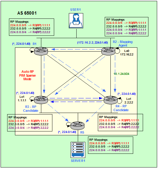
Figure 3
This is the result Multicast Groups-RP mappings on R2.
R2#show ip pim rp mapping
PIM Group-to-RP Mappings
This system is an RP-mapping agent (Loopback0)Group(s) 224.0.0.0/5
RP 1.1.1.1 (?), v2v1
Info source: 1.1.1.1 (?), elected via Auto-RP
Uptime: 00:10:15, expires: 00:02:49
Group(s) 224.0.0.0/4
RP 2.2.2.2 (?), v2v1
Info source: 2.2.2.2 (?), elected via Auto-RP
Uptime: 00:11:55, expires: 00:02:06
RP 1.1.1.1 (?), v2v1
Info source: 1.1.1.1 (?), via Auto-RP
Uptime: 00:13:16, expires: 00:02:45
Group(s) 232.0.0.0/5
RP 2.2.2.2 (?), v2v1
Info source: 2.2.2.2 (?), elected via Auto-RP
Uptime: 00:10:55, expires: 00:02:09
If we select any other router in the Multicast domain, for example R3, and we show the RP-to-Group mappings we only see the selection made by R2 (MA). We do not see R3’s mapping for 224.0.0.0/4.
R5#show ip pim rp mapping
PIM Group-to-RP MappingsGroup(s) 224.0.0.0/5
RP 1.1.1.1 (?), v2v1
Info source: 172.16.2.2 (?), elected via Auto-RP
Uptime: 00:06:31, expires: 00:02:26
Group(s) 224.0.0.0/4
RP 2.2.2.2 (?), v2v1
Info source: 172.16.2.2 (?), elected via Auto-RP
Uptime: 00:08:11, expires: 00:02:25
Group(s) 232.0.0.0/5
RP 2.2.2.2 (?), v2v1
Info source: 172.16.2.2 (?), elected via Auto-RP
Uptime: 00:07:11, expires: 00:02:26
Finally, the Multicast Routing Table shows that the RPs (R3 and R4) have successfully joined 224.0.1.39 and the MA (R2) is successfully listening on 224.0.1.39 and forwarding on 224.0.1.40.
R5#show ip mroute
IP Multicast Routing Table
Flags: D – Dense, S – Sparse, B – Bidir Group, s – SSM Group, C – Connected,
L – Local, P – Pruned, R – RP-bit set, F – Register flag,
T – SPT-bit set, J – Join SPT, M – MSDP created entry,
X – Proxy Join Timer Running, A – Candidate for MSDP Advertisement,
U – URD, I – Received Source Specific Host Report,
Z – Multicast Tunnel, z – MDT-data group sender,
Y – Joined MDT-data group, y – Sending to MDT-data group
Outgoing interface flags: H – Hardware switched, A – Assert winner
Timers: Uptime/Expires
Interface state: Interface, Next-Hop or VCD, State/Mode
(*, 224.0.1.39), 01:52:44/stopped, RP 0.0.0.0, flags: D
Incoming interface: Null, RPF nbr 0.0.0.0
Outgoing interface list:
FastEthernet0/0, Forward/Sparse, 01:52:44/00:00:00
(1.1.1.1, 224.0.1.39), 00:02:36/00:00:23, flags: PT
Incoming interface: FastEthernet0/0, RPF nbr 10.1.122.3
Outgoing interface list: Null
(2.2.2.2, 224.0.1.39), 00:00:13/00:02:46, flags: PT
Incoming interface: FastEthernet0/0, RPF nbr 10.1.122.4
Outgoing interface list: Null
(*, 224.0.1.40), 01:54:21/stopped, RP 0.0.0.0, flags: DCL
Incoming interface: Null, RPF nbr 0.0.0.0
Outgoing interface list:
FastEthernet0/0, Forward/Sparse, 01:54:21/00:00:00
(172.16.2.2, 224.0.1.40), 01:52:51/00:02:26, flags: PLTX
Incoming interface: FastEthernet0/0, RPF nbr 10.1.122.3
Outgoing interface list: Null
In this scenario, R5 does not have any other downstream PIM neighbors; this is why the Outgoing interface list (OIL) shows as Null.
User 1 Joins 224.1.1.1
User1 becomes a Receiver for the Multicast Group 224.1.1.1 by signalling with an IGMP Report message on the LAN segment. The Designated Router (DR) is going to translate the IGMP Report into a PIM Join for 224.1.1.1. The DR then checks its RP-to-Group mapping database and forwards the PIM Join to the RP allocated to that specific Multicast Group, R3.
The DR election is based on highest priority or, in case of a tie, highest IP address.
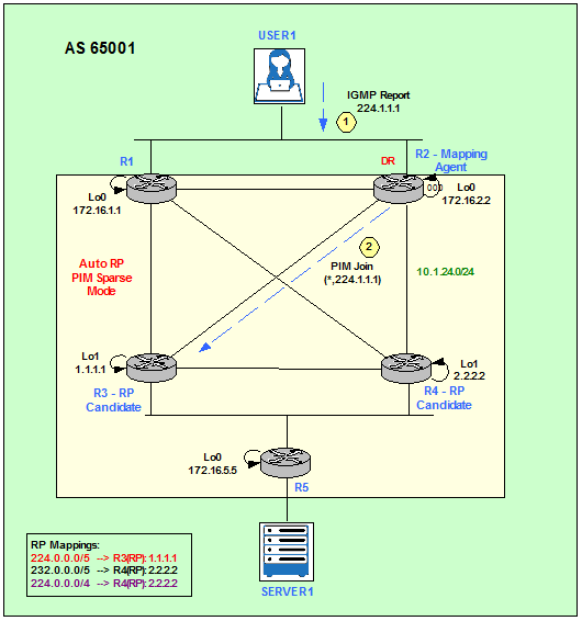
Figure 4
User 1 notifies it wants to receive Multicast traffic for 224.1.1.1 Group.
USER1(config)#interface fa0/0
USER1(config-if)#ip igmp join-group 224.1.1.1
*Mar 1 02:32:33.899: IGMP(0): Send v2 Report for 224.1.1.1 on FastEthernet0/0
USER1(config-if)#ip igmp join-group 224.1.1.1
*Mar 1 02:32:33.899: IGMP(0): Send v2 Report for 224.1.1.1 on FastEthernet0/0
R2 receives the IGMP Report from User1 and sends a PIM Join on its fa2/0 towards R3 (1.1.1.1).
*Mar 1 02:33:36.087: IGMP(0): Received v2 Report on FastEthernet0/0 from 10.1.121.100 for 224.1.1.1
*Mar 1 02:33:36.095: PIM(0): Check RP 1.1.1.1 into the (*, 224.1.1.1) entry
*Mar 1 02:33:36.095: PIM(0): Building Triggered (*,G) Join / (S,G,RP-bit) Prune message for 224.1.1.1
*Mar 1 02:33:36.095: PIM(0): Insert (*,224.1.1.1) join in nbr 10.1.23.3’s queue
*Mar 1 02:33:36.095: PIM(0): Check RP 1.1.1.1 into the (*, 224.1.1.1) entry
*Mar 1 02:33:36.095: PIM(0): Building Triggered (*,G) Join / (S,G,RP-bit) Prune message for 224.1.1.1
*Mar 1 02:33:36.095: PIM(0): Insert (*,224.1.1.1) join in nbr 10.1.23.3’s queue
R3 receives the PIM Join from R2 and adds fa2/0 into the OIL list.
*Mar 1 02:32:07.411: PIM(0): Received v2 Join/Prune on FastEthernet2/0 from 10.1.23.2, to us
*Mar 1 02:32:07.411: PIM(0): Join-list: (*, 224.1.1.1), RPT-bit set, WC-bit set, S-bit set
*Mar 1 02:32:07.415: PIM(0): Check RP 1.1.1.1 into the (*, 224.1.1.1) entry
*Mar 1 02:32:07.415: PIM(0): Add FastEthernet2/0/10.1.23.2 to (*, 224.1.1.1), Forward state, by PIM *G Join
*Mar 1 02:32:07.411: PIM(0): Join-list: (*, 224.1.1.1), RPT-bit set, WC-bit set, S-bit set
*Mar 1 02:32:07.415: PIM(0): Check RP 1.1.1.1 into the (*, 224.1.1.1) entry
*Mar 1 02:32:07.415: PIM(0): Add FastEthernet2/0/10.1.23.2 to (*, 224.1.1.1), Forward state, by PIM *G Join
At this point we can see that only the DR (R2) and the RP (R3) know about the (*,G) = (*,224.1.1.1).
R1#show ip mroute 224.1.1.1
Group 224.1.1.1 not found
Group 224.1.1.1 not found
R2#show ip mroute 224.1.1.1
IP Multicast Routing Table
Flags: D – Dense, S – Sparse, B – Bidir Group, s – SSM Group, C – Connected,
L – Local, P – Pruned, R – RP-bit set, F – Register flag,
T – SPT-bit set, J – Join SPT, M – MSDP created entry,
X – Proxy Join Timer Running, A – Candidate for MSDP Advertisement,
U – URD, I – Received Source Specific Host Report,
Z – Multicast Tunnel, z – MDT-data group sender,
Y – Joined MDT-data group, y – Sending to MDT-data group
Outgoing interface flags: H – Hardware switched, A – Assert winner
Timers: Uptime/Expires
Interface state: Interface, Next-Hop or VCD, State/Mode
(*, 224.1.1.1), 00:08:04/00:02:46, RP 1.1.1.1, flags: SJC
Incoming interface: FastEthernet2/0, RPF nbr 10.1.23.3
Outgoing interface list:
FastEthernet0/0, Forward/Sparse, 00:00:13/00:02:46
R3#show ip mroute 224.1.1.1
IP Multicast Routing Table
Flags: D – Dense, S – Sparse, B – Bidir Group, s – SSM Group, C – Connected,
L – Local, P – Pruned, R – RP-bit set, F – Register flag,
T – SPT-bit set, J – Join SPT, M – MSDP created entry,
X – Proxy Join Timer Running, A – Candidate for MSDP Advertisement,
U – URD, I – Received Source Specific Host Report,
Z – Multicast Tunnel, z – MDT-data group sender,
Y – Joined MDT-data group, y – Sending to MDT-data group
Outgoing interface flags: H – Hardware switched, A – Assert winner
Timers: Uptime/Expires
Interface state: Interface, Next-Hop or VCD, State/Mode
(*, 224.1.1.1), 00:07:13/00:03:12, RP 1.1.1.1, flags: S
Incoming interface: Null, RPF nbr 0.0.0.0
Outgoing interface list:
FastEthernet1/0, Forward/Sparse, 00:07:13/00:03:12
R4#show ip mroute 224.1.1.1
Group 224.1.1.1 not found
Group 224.1.1.1 not found
R5#show ip mroute 224.1.1.1
Group 224.1.1.1 not found
Group 224.1.1.1 not found
Server1 sends Multicast Traffic to 224.1.1.1
Figure 5 describes the Registration proccess of a Multicast Source for the Group 224.1.1.1.
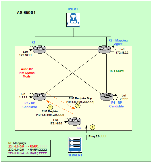
Figure 5
Server1 generates some traffic and we can verify that User1 is receiving it because is replying to the pings.
SERVER1#ping 224.1.1.1 repeat 5
Type escape sequence to abort.
Sending 5, 100-byte ICMP Echos to 224.1.1.1, timeout is 2 seconds:
Reply to request 0 from 10.1.121.100, 1460 ms
Reply to request 1 from 10.1.121.100, 68 ms
Reply to request 2 from 10.1.121.100, 48 ms
Reply to request 3 from 10.1.121.100, 88 ms
Reply to request 4 from 10.1.121.100, 40 ms
Reply to request 5 from 10.1.121.100, 52 ms
When R5 receives Server1’s pings to a Multicast Group, it generates a PIM Register message (S,G) = (10.1.5.100,224.1.1.1) towards the RP assigned to that particular Multicast Group, R3 in our example.
*Mar 1 02:43:32.791: PIM(0): Check RP 1.1.1.1 into the (*, 224.1.1.1) entry
*Mar 1 02:43:32.795: PIM(0): Send v2 Register to 1.1.1.1 for 10.1.5.100, group 224.1.1.1
*Mar 1 02:43:34.875: PIM(0): Received v2 Join/Prune on FastEthernet0/0 from 10.1.122.3, to us
*Mar 1 02:43:34.875: PIM(0): Join-list: (10.1.5.100/32, 224.1.1.1), S-bit set
*Mar 1 02:43:32.795: PIM(0): Send v2 Register to 1.1.1.1 for 10.1.5.100, group 224.1.1.1
*Mar 1 02:43:34.875: PIM(0): Received v2 Join/Prune on FastEthernet0/0 from 10.1.122.3, to us
*Mar 1 02:43:34.875: PIM(0): Join-list: (10.1.5.100/32, 224.1.1.1), S-bit set
The RP, R3, replies with a Register Stop and updates its Multicast Routing Table.
*Mar 1 02:45:26.503: PIM(0): Received v2 Register on FastEthernet0/0 from 10.1.122.5
*Mar 1 02:45:26.503: for 10.1.5.100, group 224.1.1.1
*Mar 1 02:45:26.507: PIM(0): Forward decapsulated data packet for 224.1.1.1 on FastEthernet2/0
*Mar 1 02:45:26.567: PIM(0): Insert (10.1.5.100,224.1.1.1) join in nbr 10.1.122.5’s queue
*Mar 1 02:45:26.567: PIM(0): Building Join/Prune packet for nbr 10.1.122.5
*Mar 1 02:45:26.567: PIM(0): Adding v2 (10.1.5.100/32, 224.1.1.1), S-bit Join
*Mar 1 02:45:26.571: PIM(0): Send v2 join/prune to 10.1.122.5 (FastEthernet0/0)
*Mar 1 02:45:27.959: PIM(0): Join-list: (10.1.5.100/32, 224.1.1.1), S-bit set
Now we check who knows about (S,G) = (10.1.5.100,224.1.1.1) querying the Multicast Routing Table. We can see that only the routers in the path between Server1 and RP (R3) know about the (S,G) pair.
R5#show ip mroute 224.1.1.1
[…]
(*, 224.1.1.1), 00:05:36/stopped, RP 1.1.1.1, flags: SPF
Incoming interface: FastEthernet0/0, RPF nbr 10.1.122.3
Outgoing interface list: Null
[…]
(*, 224.1.1.1), 00:05:36/stopped, RP 1.1.1.1, flags: SPF
Incoming interface: FastEthernet0/0, RPF nbr 10.1.122.3
Outgoing interface list: Null
(10.1.5.100, 224.1.1.1), 00:00:07/00:03:26, flags: FT
Incoming interface: FastEthernet0/1, RPF nbr 0.0.0.0
Outgoing interface list:
FastEthernet0/0, Forward/Sparse, 00:00:07/00:03:24
R3#show ip mroute 224.1.1.1
[…]
(*, 224.1.1.1), 00:06:57/00:03:06, RP 1.1.1.1, flags: S
Incoming interface: Null, RPF nbr 0.0.0.0
Outgoing interface list:
FastEthernet2/0, Forward/Sparse, 00:06:50/00:03:06
[…]
(*, 224.1.1.1), 00:06:57/00:03:06, RP 1.1.1.1, flags: S
Incoming interface: Null, RPF nbr 0.0.0.0
Outgoing interface list:
FastEthernet2/0, Forward/Sparse, 00:06:50/00:03:06
(10.1.5.100, 224.1.1.1), 00:00:33/00:03:22, flags: T
Incoming interface: FastEthernet0/0, RPF nbr 10.1.122.5
Outgoing interface list:
FastEthernet2/0, Forward/Sparse, 00:00:33/00:03:06
R4#show ip mroute 224.1.1.1
[…]
(*, 224.1.1.1), 00:00:56/00:02:03, RP 1.1.1.1, flags: SP
Incoming interface: FastEthernet1/0, RPF nbr 10.1.34.3
Outgoing interface list: Null
[…]
(*, 224.1.1.1), 00:00:56/00:02:03, RP 1.1.1.1, flags: SP
Incoming interface: FastEthernet1/0, RPF nbr 10.1.34.3
Outgoing interface list: Null
R2#show ip mroute 224.1.1.1
[…]
(*, 224.1.1.1), 00:07:30/stopped, RP 1.1.1.1, flags: SJC
Incoming interface: FastEthernet2/0, RPF nbr 10.1.23.3
Outgoing interface list:
FastEthernet0/0, Forward/Sparse, 00:07:30/00:02:28
[…]
(*, 224.1.1.1), 00:07:30/stopped, RP 1.1.1.1, flags: SJC
Incoming interface: FastEthernet2/0, RPF nbr 10.1.23.3
Outgoing interface list:
FastEthernet0/0, Forward/Sparse, 00:07:30/00:02:28
R1#show ip mroute 224.1.1.1
[…]
(*, 224.1.1.1), 02:09:56/00:02:06, RP 1.1.1.1, flags: SP
Incoming interface: FastEthernet2/0, RPF nbr 10.1.14.4
Outgoing interface list: Null
[…]
(*, 224.1.1.1), 02:09:56/00:02:06, RP 1.1.1.1, flags: SP
Incoming interface: FastEthernet2/0, RPF nbr 10.1.14.4
Outgoing interface list: Null
Building the Shortest-Path Tree (SPT)
The RP, R3 for 224.1.1.1, is going to merge the two trees together sending its own PIM Join (10.1.5.100, 224.1.1.1) towards Server1 in order to notify the devices in the path that it wants to receive the Multicast traffic. Now the SPT is built from the Server1 to R3 (RP). Then the Shared Tree (RPT) is built from R3 to User1, the Receiver. R3 is then receiving the Multicast traffic inbound from the SPT and sending it outbound on the RPT down to the Receiver. The last hop router, R2, can switchover to the SPT sending a PIM Join (10.1.5.100, 224.1.1.1) towards the Source, Server1, and a PIM Prune (*,224.1.1.1) towards R3, the RP. User1 is now joined the SPT (10.1.5.100, 224.1.1.1).
Note that in order to clearly appreciate the switchover of R2 from the RPT to the SPT we have made the link between R2 and R4 more preferred than the link between R2 and R3. This way we can appreciate that the RP, R3, is not longer in the data plane.
R2(config)#interface fa1/0
R2(config-if)#ip ospf cost 999
R2(config)#interface fa2/0
R2(config-if)#ip ospf cost 999
R2(config-if)#ip ospf cost 999
R2(config)#interface fa2/0
R2(config-if)#ip ospf cost 999
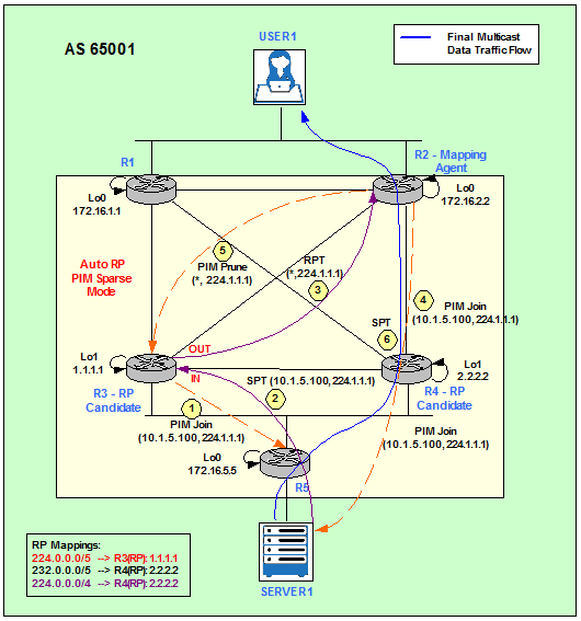
Figure 6
The debup ip pim shows how R2 sends a PIM Join in order to join the SPT (10.1.5.100, 224.1.1.1).
*Mar 1 03:45:59.619: PIM(0): Insert (10.1.5.100,224.1.1.1) join in nbr 10.1.24.4’s queue
*Mar 1 03:45:59.623: PIM(0): Building Join/Prune packet for nbr 10.1.24.4
*Mar 1 03:45:59.623: PIM(0): Adding v2 (10.1.5.100/32, 224.1.1.1), S-bit Join
*Mar 1 03:45:59.623: PIM(0): Send v2 join/prune to 10.1.24.4 (FastEthernet0/1)
*Mar 1 03:45:59.623: PIM(0): Building Join/Prune packet for nbr 10.1.24.4
*Mar 1 03:45:59.623: PIM(0): Adding v2 (10.1.5.100/32, 224.1.1.1), S-bit Join
*Mar 1 03:45:59.623: PIM(0): Send v2 join/prune to 10.1.24.4 (FastEthernet0/1)
R2#show ip mroute 224.1.1.1
IP Multicast Routing Table
Flags: D – Dense, S – Sparse, B – Bidir Group, s – SSM Group, C – Connected,
L – Local, P – Pruned, R – RP-bit set, F – Register flag,
T – SPT-bit set, J – Join SPT, M – MSDP created entry,
X – Proxy Join Timer Running, A – Candidate for MSDP Advertisement,
U – URD, I – Received Source Specific Host Report,
Z – Multicast Tunnel, z – MDT-data group sender,
Y – Joined MDT-data group, y – Sending to MDT-data group
Outgoing interface flags: H – Hardware switched, A – Assert winner
Timers: Uptime/Expires
Interface state: Interface, Next-Hop or VCD, State/Mode
(*, 224.1.1.1), 00:01:39/stopped, RP 1.1.1.1, flags: SJC
Incoming interface: FastEthernet0/1, RPF nbr 10.1.24.4
Outgoing interface list:
FastEthernet0/0, Forward/Sparse, 00:01:39/00:02:11
(10.1.5.100, 224.1.1.1), 00:01:25/00:02:57, flags: JT
Incoming interface: FastEthernet0/1, RPF nbr 10.1.24.4
Outgoing interface list:
FastEthernet0/0, Forward/Sparse, 00:01:25/00:02:11
If we run a mtrace on R2 towards the Multicast Source, we see that R3 (RP) is not longer in the data plane.
R2#mtrace 10.1.5.100
Type escape sequence to abort.
Mtrace from 10.1.5.100 to 10.1.24.2 via RPF
From source (?) to destination (?)
Querying full reverse path…
0 10.1.24.2
-1 10.1.24.2 PIM [10.1.5.0/24]
-2 10.1.24.4 PIM [10.1.5.0/24]
-3 10.1.122.5 PIM [10.1.5.0/24]
-4 10.1.5.100
Type escape sequence to abort.
Mtrace from 10.1.5.100 to 10.1.24.2 via RPF
From source (?) to destination (?)
Querying full reverse path…
0 10.1.24.2
-1 10.1.24.2 PIM [10.1.5.0/24]
-2 10.1.24.4 PIM [10.1.5.0/24]
-3 10.1.122.5 PIM [10.1.5.0/24]
-4 10.1.5.100
Designated Router (DR) Election
As I mentioned before, the DR translates IGMP Reports from Receivers into PIM Joins towards the RP. The DR checks its RP-to-Group mapping database to find out the RP associated to the Multicast Group and sends the PIM Join (*,G).
The DR election is based on highest priority or, in case of a tie, highest IP address.
The DR for the segment 10.1.121.0/24 (R1, R2, User1) is R2.
R1#show ip pim interface fa0/0
Address Interface Ver/ Nbr Query DR DR
Mode Count Intvl Prior
10.1.121.1 FastEthernet0/0 v2/S 1 30 1 10.1.121.2
R2#show ip pim interface fa0/0
Address Interface Ver/ Nbr Query DR DR
Mode Count Intvl Prior
10.1.121.2 FastEthernet0/0 v2/S 1 30 1 10.1.121.2
To make R1 the DR we can change the priority to a higher value.
R1(config)#interface fa0/0
R1(config-if)#ip pim dr-priority 100
*Mar 1 00:33:11.015: %PIM-5-DRCHG: DR change from neighbor 10.1.121.2 to 10.1.121.1 on interface FastEthernet0/0
R1(config-if)#ip pim dr-priority 100
*Mar 1 00:33:11.015: %PIM-5-DRCHG: DR change from neighbor 10.1.121.2 to 10.1.121.1 on interface FastEthernet0/0
R1#show ip pim interface fa0/0Address Interface Ver/ Nbr Query DR DR
Mode Count Intvl Prior
10.1.121.1 FastEthernet0/0 v2/S 1 30 100 10.1.121.1
R2#show ip pim interface fa0/0
Address Interface Ver/ Nbr Query DR DR
Mode Count Intvl Prior
10.1.121.2 FastEthernet0/0 v2/S 1 30 1 10.1.121.1
PIM Assert Mechanism – Forwarder Election
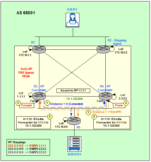
Figure 7
PIM uses Assert messages to elect the single router that forwards the data traffic to the LAN. When both R3 and R4 forward the data traffic for channel (S,G) or (*,G), R3 receives R4’s data traffic and R4 receives R3’s data traffic on their downstream interfaces. This condition triggers the Assert on the downstream interfaces. To start with, R3 and R4 will assume that they are Assert-winners and send out the PIM Assert message.
All the routers on the LAN will carry out the election based on the PIM Assert messages. PIM Assert messages contain Group address, Source address, RPT bit and route metric for the Source in case of (S,G) or RP in case of (*,G).
The election is based on the following order:
- If a router has (S,G) state and others have (*,G) state, router having (S,G) state wins. RPT bit in the message identifies this.
- Router with lower Administrative Distance (AD) wins.
- Router with lower unicast route metric wins.
- Router with the highest IP address wins.
The election algorithm is such that there will always be only one winner.
In our topology shown in Figure 7, R3 wins the Assert election for (1.1.1.1, 224.0.1.39). Its AD to the RP Address 1.1.1.1 (R3’s Loopback1) is lower than R4’s AD: 0 (connected) < 110 (OSPF).
R3#show ip route 1.1.1.1
Routing entry for 1.1.1.1/32
Known via “connected“, distance 0, metric 0 (connected, via interface)
Routing Descriptor Blocks:
* directly connected, via Loopback1
Route metric is 0, traffic share count is 1
Routing entry for 1.1.1.1/32
Known via “connected“, distance 0, metric 0 (connected, via interface)
Routing Descriptor Blocks:
* directly connected, via Loopback1
Route metric is 0, traffic share count is 1
R4#show ip route 1.1.1.1
Routing entry for 1.1.1.1/32
Known via “ospf 1“, distance 110, metric 2, type intra area
Last update from 10.1.34.3 on FastEthernet1/0, 00:15:55 ago
Routing Descriptor Blocks:
* 10.1.34.3, from 172.16.3.3, 00:15:55 ago, via FastEthernet1/0
Route metric is 2, traffic share count is 1
Routing entry for 1.1.1.1/32
Known via “ospf 1“, distance 110, metric 2, type intra area
Last update from 10.1.34.3 on FastEthernet1/0, 00:15:55 ago
Routing Descriptor Blocks:
* 10.1.34.3, from 172.16.3.3, 00:15:55 ago, via FastEthernet1/0
Route metric is 2, traffic share count is 1
So from now onwards, router R4 stops forwarding data traffic.
R3#
*Mar 1 00:04:08.935: PIM(0): Assert metric to source 1.1.1.1 is [110/2]
*Mar 1 00:04:08.935: PIM(0): We win, our metric [0/0]
*Mar 1 00:04:08.935: PIM(0): Update FastEthernet0/0/10.1.122.4 to (1.1.1.1, 224.0.1.39), Forward state, by PIM Assert
*Mar 1 00:04:08.935: PIM(0): Changed FastEthernet0/0 from Prune to Forward state
*Mar 1 00:04:08.935: PIM(0): (1.1.1.1/32, 224.0.1.39) oif FastEthernet0/0 in Forward state
R4#
*Mar 1 00:04:01.659: PIM(0): Received v2 Assert on FastEthernet0/0 from 10.1.122.3
*Mar 1 00:04:01.663: PIM(0): Assert metric to source 1.1.1.1 is [0/0]
*Mar 1 00:04:01.663: PIM(0): We lose, our metric [110/2]
*Mar 1 00:04:01.663: PIM(0): Insert (1.1.1.1,224.0.1.39) prune in nbr 10.1.122.3’s queue
*Mar 1 00:04:01.663: PIM(0): Send (1.1.1.1, 224.0.1.39) PIM-DM prune to oif FastEthernet0/0 in Prune state
*Mar 1 00:04:01.667: PIM(0): (1.1.1.1/32, 224.0.1.39) oif FastEthernet0/0 in Prune state
*Mar 1 00:04:01.667: PIM(0): Building Join/Prune packet for nbr 10.1.122.3
*Mar 1 00:04:01.667: PIM(0): Adding v2 (1.1.1.1/32, 224.0.1.39) Prune
*Mar 1 00:04:01.667: PIM(0): Send v2 join/prune to 10.1.122.3 (FastEthernet0/0)
R4 stores the Assert-winner and its Assert-metric for future use.
R4#show ip mroute
[…]
(1.1.1.1, 224.0.1.39), 00:12:47/00:02:29, flags: T
Incoming interface: FastEthernet1/0, RPF nbr 10.1.34.3
Outgoing interface list:
FastEthernet0/0, Prune/Sparse, 00:00:31/00:02:28
FastEthernet0/1, Forward/Sparse, 00:12:47/00:00:00
FastEthernet2/0, Forward/Sparse, 00:12:47/00:00:00
[…]
(1.1.1.1, 224.0.1.39), 00:12:47/00:02:29, flags: T
Incoming interface: FastEthernet1/0, RPF nbr 10.1.34.3
Outgoing interface list:
FastEthernet0/0, Prune/Sparse, 00:00:31/00:02:28
FastEthernet0/1, Forward/Sparse, 00:12:47/00:00:00
FastEthernet2/0, Forward/Sparse, 00:12:47/00:00:00
R3#show ip mroute
[…]
(1.1.1.1, 224.0.1.39), 00:13:58/00:02:14, flags: T
Incoming interface: Loopback1, RPF nbr 0.0.0.0
Outgoing interface list:
FastEthernet0/1, Prune/Sparse, 00:00:47/00:02:12, A
FastEthernet1/0, Forward/Sparse, 00:13:57/00:00:00
FastEthernet0/0, Forward/Sparse, 00:00:44/00:02:15, A
FastEthernet2/0, Forward/Sparse, 00:13:58/00:00:00, A
So R5 sends their periodic PIM Join messages for (1.1.1.1, 224.0.1.39) to R3, the Assert-winner.
R5#
*Mar 1 00:04:01.099: PIM(0): Received v2 Assert on FastEthernet0/0 from 10.1.122.3
*Mar 1 00:04:01.099: PIM(0): Assert metric to source 1.1.1.1 is [0/0]
*Mar 1 00:04:01.099: PIM(0): Cached metric is [0/0]
*Mar 1 00:04:01.115: PIM(0): Received v2 Join/Prune on FastEthernet0/0 from 10.1.122.4, not to us
*Mar 1 00:04:01.115: PIM(0): Prune-list: (1.1.1.1/32, 224.0.1.39)
*Mar 1 00:04:01.115: PIM(0): Canceling RPF prune on FastEthernet0/0 for (1.1.1.1, 224.0.1.39)
R5#mtrace 1.1.1.1
Type escape sequence to abort.
Mtrace from 1.1.1.1 to 10.1.122.5 via RPF
From source (?) to destination (?)
Querying full reverse path…
0 10.1.122.5
-1 10.1.122.5 PIM [1.1.1.1/32]
-2 10.1.122.3 PIM [1.1.1.1/32]
-3 1.1.1.1
AS65002 Physical Topology
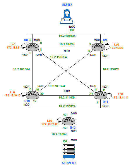
Figure 8
AS65002 Multicast Topology – Bootstrap Router (BSR)
AS 65002 is running PIM SM on all links. Bootstrap router (BSR) protocol is enabled to dynamically distribute RP information to other routers in the PIM SM domain. It is a standard-based protocol available with PIMv2.
As it is shown in Figure 9, R10 an R11 are the candidate RPs and R9 is the Bootstrap Router (similar to MA role in Auto-RP).
Unlike Auto-RP, BSR does not use any dense-mode Groups to flood candidate RP and RP mapping information. Instead, the information is flooded using PIM messages, on hop-by-hop basis. R9 (BSR) listens to candidate RP announcements from R10 and R11. Unlike Auto-RP MA, the BSR does not elect the best RP for every Group range it learns about. Instead of this, for every Group range known, the BSR builds a set of candidate RPs, including all routers that advertised their willingness to service this range. The resulting array of Group range to RP set mappings is distributed by the BSR using PIM messages to all routers in AS 65002. Then every Multicast router in the domain uses this information to populate their RP caches.
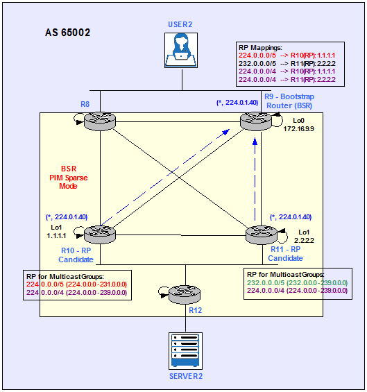
Figure 9
We enable ip multicast-routing in configuration mode on all routers and ip pim sparse-mode at interface level on all routers’ interfaces.
R8 – R12:
R#conf t
R(config)#ip multicast-routing
R(config)#interface FastEthernet X/Y
R(config-if)#ip pim sparse-mode
R(config)#ip multicast-routing
R(config)#interface FastEthernet X/Y
R(config-if)#ip pim sparse-mode
R10 is the candidate RP for 224.0.0.0/5 (224.0.0.0 – 231.0.0.0) and the whole Multicast range 224.0.0.0/4.
R10(config)#ip access-list standard MULTICAST_GROUPS
R10(config-std-nacl)#permit 224.0.0.0 7.255.255.255
R10(config-std-nacl)#permit 224.0.0.0 15.255.255.255
R10(config-std-nacl)#permit 224.0.0.0 7.255.255.255
R10(config-std-nacl)#permit 224.0.0.0 15.255.255.255
R10(config)# interface Loopback1
R10(config)# ip address 2.2.2.2 255.255.255.255
R10(config-if)# ip pim sparse-mode
R10(config)#ip pim rp-candidate lo1 group-list MULTICAST_GROUPS
R11 is the candidate RP for 232.0.0.0/5 (232.0.0.0 – 239.0.0.0) and the whole Multicast range 224.0.0.0/4.
R11(config)#ip access-list standard MULTICAST_GROUPS
R11(config-std-nacl)#permit 232.0.0.0 7.255.255.255
R11(config-std-nacl)#permit 224.0.0.0 15.255.255.255
R11(config-std-nacl)#permit 232.0.0.0 7.255.255.255
R11(config-std-nacl)#permit 224.0.0.0 15.255.255.255
R11(config)# interface Loopback1
R11(config)# ip address 2.2.2.2 255.255.255.255
R11(config-if)# ip pim sparse-mode
R11(config)#ip pim rp-candidate lo1 group-list MULTICAST_GROUPS
R9 is configured to be the BSR and receives the RP-to-Group mappings from R10 and R11. Then, R9 advertises the RP-to-Group mappings received to all routers in the Multicast domain.
R9(config)# interface Loopback0
R9(config)# ip address 172.16.9.9 255.255.255.255
R9(config-if)# ip pim sparse-mode
R9(config)# ip address 172.16.9.9 255.255.255.255
R9(config-if)# ip pim sparse-mode
R9(config)#ip pim bsr-candidate lo0 0
Figure 10 shows the BSR discovery process.
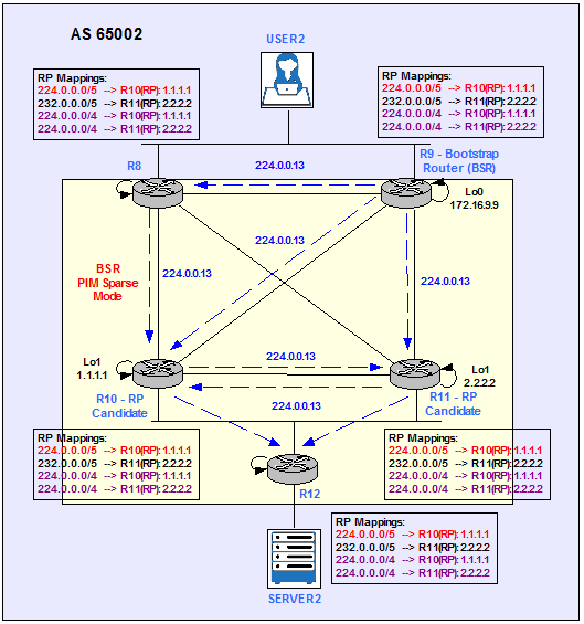
Figure 10
These are the RP-to-Group mappings on R9.
R9#show ip pim rp mapping
PIM Group-to-RP Mappings
This system is the Bootstrap Router (v2)Group(s) 224.0.0.0/5
RP 1.1.1.1 (?), v2
Info source: 10.2.109.10 (?), via bootstrap, priority 0, holdtime 150
Uptime: 00:03:52, expires: 00:01:35
Group(s) 224.0.0.0/4
RP 2.2.2.2 (?), v2
Info source: 10.2.111.11 (?), via bootstrap, priority 0, holdtime 150
Uptime: 00:04:02, expires: 00:02:25
RP 1.1.1.1 (?), v2
Info source: 10.2.109.10 (?), via bootstrap, priority 0, holdtime 150
Uptime: 00:03:52, expires: 00:01:37
Group(s) 232.0.0.0/5
RP 2.2.2.2 (?), v2
Info source: 10.2.111.11 (?), via bootstrap, priority 0, holdtime 150
Uptime: 00:04:02, expires: 00:02:23
If we select any other router in the Multicast domain, for example R8, and show the RP-to-Group mappings we see the same output.
R8#show ip pim rp mapping
PIM Group-to-RP MappingsGroup(s) 224.0.0.0/5
RP 1.1.1.1 (?), v2
Info source: 172.16.9.9 (?), via bootstrap, priority 0, holdtime 150
Uptime: 00:00:01, expires: 00:02:26
Group(s) 224.0.0.0/4
RP 2.2.2.2 (?), v2
Info source: 172.16.9.9 (?), via bootstrap, priority 0, holdtime 150
Uptime: 00:00:01, expires: 00:02:24
RP 1.1.1.1 (?), v2
Info source: 172.16.9.9 (?), via bootstrap, priority 0, holdtime 150
Uptime: 00:00:01, expires: 00:02:24
Group(s) 232.0.0.0/5
RP 2.2.2.2 (?), v2
Info source: 172.16.9.9 (?), via bootstrap, priority 0, holdtime 150
Uptime: 00:00:01, expires: 00:02:27
User 2 Joins 234.2.2.2
User2 becomes a Receiver for the Multicast Group 234.2.2.2 by signalling with an IGMP Report message on the LAN segment . The DR, R9, is going to translate the IGMP Report into a PIM Join for 234.2.2.2. R9 then checks its RP-to-Group mapping database and forwards the PIM Join to R11, which is the RP allocated to that specific Multicast Group.
USER2(config)#interface fa0/0
USER2(config-if)#ip igmp join-group 234.2.2.2
USER2(config-if)#ip igmp join-group 234.2.2.2
R11 now has the (*, 234.2.2.2) entry in its Multicast Routing Table.
R11#show ip mroute 234.2.2.2
[…]
(*, 234.2.2.2), 00:01:07/00:03:20, RP 2.2.2.2, flags: S
Incoming interface: Null, RPF nbr 0.0.0.0
Outgoing interface list:
FastEthernet1/0, Forward/Sparse, 00:01:07/00:03:20
[…]
(*, 234.2.2.2), 00:01:07/00:03:20, RP 2.2.2.2, flags: S
Incoming interface: Null, RPF nbr 0.0.0.0
Outgoing interface list:
FastEthernet1/0, Forward/Sparse, 00:01:07/00:03:20
Server 2 sends Multicast Traffic to 234.2.2.2
Server2 generates some traffic and we can verify that User2 is receiving it because is replying to the pings.
SERVER2#ping 234.2.2.2 repeat 5
Type escape sequence to abort.
Sending 5, 100-byte ICMP Echos to 234.2.2.2, timeout is 2 seconds:Reply to request 0 from 10.2.189.100, 48 ms
Reply to request 0 from 10.2.189.100, 68 ms
Reply to request 1 from 10.2.189.100, 84 ms
Reply to request 2 from 10.2.189.100, 84 ms
Reply to request 3 from 10.2.189.100, 88 ms
Reply to request 4 from 10.2.189.100, 88 ms
When R12 receives Server2’s pings to a Multicast Group, it generates a PIM Register message (S,G) = (10.2.12.100, 234.2.2.2) towards the RP assigned to that particular Multicast Group, R11 in our example. R11 replies with a Register Stop and updates its Multicast Routing Table.
R11#show ip mroute 234.2.2.2
[…]
(*, 234.2.2.2), 00:03:11/00:03:16, RP 2.2.2.2, flags: S
Incoming interface: Null, RPF nbr 0.0.0.0
Outgoing interface list:
FastEthernet1/0, Forward/Sparse, 00:03:11/00:03:16
[…]
(*, 234.2.2.2), 00:03:11/00:03:16, RP 2.2.2.2, flags: S
Incoming interface: Null, RPF nbr 0.0.0.0
Outgoing interface list:
FastEthernet1/0, Forward/Sparse, 00:03:11/00:03:16
(10.2.12.100, 234.2.2.2), 00:01:03/00:02:07, flags: PT
Incoming interface: FastEthernet0/0, RPF nbr 10.2.112.12
Outgoing interface list: Null
Building the Shortest-Path Tree (SPT)
The RP, R11 for 234.2.2.2, is going to merge the two trees together: SPT and RPT (See Figure 11). For more detailed information check “Building the Shortest-Path Tree (SPT)” section for AS6001.
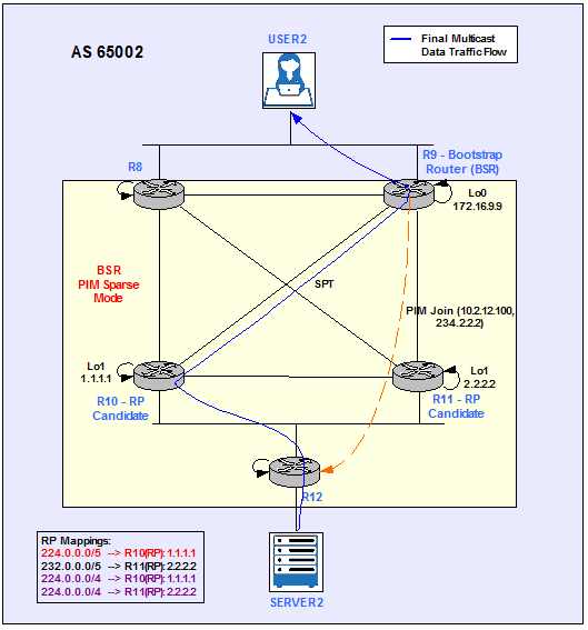
Figure 11
R11 is not longer in the Data Plane.
R9#mtrace 10.2.12.100
Type escape sequence to abort.
Mtrace from 10.2.12.100 to 10.2.109.9 via RPF
From source (?) to destination (?)
Querying full reverse path…
0 10.2.109.9
-1 10.2.109.9 PIM [10.2.12.0/24]
-2 10.2.109.10 PIM [10.2.12.0/24]
-3 10.2.112.12 PIM [10.2.12.0/24]
-4 10.2.12.100
Type escape sequence to abort.
Mtrace from 10.2.12.100 to 10.2.109.9 via RPF
From source (?) to destination (?)
Querying full reverse path…
0 10.2.109.9
-1 10.2.109.9 PIM [10.2.12.0/24]
-2 10.2.109.10 PIM [10.2.12.0/24]
-3 10.2.112.12 PIM [10.2.12.0/24]
-4 10.2.12.100
Merge AS65001 and AS65002 – Physical Topology
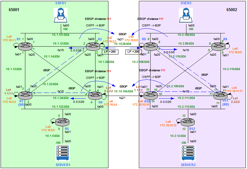
Figure 12
R2 configuration.
router ospf 1
passive-interface FastEthernet2/1
default-information originate always
passive-interface FastEthernet2/1
default-information originate always
route-map SET_LP permit 10
set local-preference 200
route-map SET_LP permit 20
router bgp 65001
bgp router-id 172.16.2.2
neighbor 10.10.28.8 remote-as 65002
neighbor 172.16.3.3 remote-as 65001
neighbor 172.16.3.3 update-source Loopback0
neighbor 172.16.3.3 next-hop-self
address-family ipv4
redistribute ospf 1
neighbor 10.10.28.8 activate
neighbor 10.10.28.8 route-map SET_LP in
neighbor 172.16.3.3 activate
distance bgp 111 200 20
exit-address-family
R3 configuration.
router bgp 65001
bgp router-id 172.16.3.3
neighbor IBGP_PEERS peer-group
neighbor IBGP_PEERS remote-as 65001
neighbor IBGP_PEERS update-source Loopback0
neighbor 172.16.2.2 peer-group IBGP_PEERS
neighbor 172.16.4.4 peer-group IBGP_PEERS
!
address-family ipv4
neighbor IBGP_PEERS route-reflector-client
neighbor 172.16.2.2 activate
neighbor 172.16.4.4 activate
exit-address-family
R4 configuration.
router ospf 1
passive-interface FastEthernet2/1
default-information originate always
passive-interface FastEthernet2/1
default-information originate always
router bgp 65001
bgp router-id 172.16.4.4
neighbor 10.10.104.10 remote-as 65002
neighbor 172.16.3.3 remote-as 65001
neighbor 172.16.3.3 update-source Loopback0
neighbor 172.16.3.3 next-hop-self
address-family ipv4
redistribute ospf 1
neighbor 10.10.104.10 activate
neighbor 172.16.3.3 activate
distance bgp 111 200 20
R8 configuration.
router ospf 2
passive-interface FastEthernet2/1
default-information originate always
passive-interface FastEthernet2/1
default-information originate always
route-map SET_LP permit 10
set local-preference 200
route-map SET_LP permit 20
router bgp 65002
bgp router-id 172.16.8.8
neighbor 10.10.28.2 remote-as 65001
neighbor 172.16.11.11 remote-as 65002
neighbor 172.16.11.11 update-source Loopback0
neighbor 172.16.11.11 next-hop-self
address-family ipv4
redistribute ospf 2
neighbor 10.10.28.2 activate
neighbor 10.10.28.2 route-map SET_LP in
neighbor 172.16.11.11 activate
distance bgp 111 200 20
R10 configuration.
router ospf 2
passive-interface FastEthernet2/1
default-information originate always
passive-interface FastEthernet2/1
default-information originate always
router bgp 65002
bgp router-id 172.16.10.10
neighbor 10.10.104.4 remote-as 65001
neighbor 172.16.11.11 remote-as 65002
neighbor 172.16.11.11 update-source Loopback0
neighbor 172.16.11.11 next-hop-self
address-family ipv4
redistribute ospf 2
neighbor 10.10.104.4 activate
neighbor 172.16.11.11 activate
distance bgp 111 200 20
R11 configuration.
router bgp 65002
bgp router-id 172.16.11.11
neighbor IBGP_PEERS peer-group
neighbor IBGP_PEERS remote-as 65002
neighbor IBGP_PEERS update-source Loopback0
neighbor 172.16.8.8 peer-group IBGP_PEERS
neighbor 172.16.10.10 peer-group IBGP_PEERS
!
address-family ipv4
neighbor IBGP_PEERS route-reflector-client
neighbor 172.16.8.8 activate
neighbor 172.16.10.10 activate
exit-address-family
Merge AS65001 and AS65002 – Multicast Topology
Anycast and Multicast Source Discovery Protocol (MSDP)
In the PIM SM model, Multicast Sources and Receivers must register with their local RP. RPs in other domains have no way of knowing about Sources located in other domains. MSDP solves this problem.
MSDP is a mechanism that allows RPs to share information about active Sources. RPs know about the Receivers in their local domain. When RPs in remote domains hear about the active Sources, they can pass on that information to their local Receivers and Multicast data can then be forwarded between the domains. PIM SM is still used to forward the traffic between the Multicast domains and needs to be enabled on the links between ASs.
The RP in each domain establishes a MSDP peering session using a TCP connection with the RPs in other domains or with border routers leading to the other domains. When the RP learns about a new Multicast Source within its own domain (through the normal PIM Register mechanism), the RP encapsulates the first data packet in a Source-Active (SA) message and sends the SA to all MSDP peers. The SA is forwarded by each Receiving peer using a modified RPF check, until the SA reaches every MSDP router in the interconnected networks. If the receiving MSDP peer is an RP, and the RP has a (*, G) entry for the group in the SA (there is an interested Receiver), the RP creates (S, G) state for the Source and joins to the SPT for the Source. The encapsulated data is decapsulated and forwarded down the shared tree (RPT) of that RP. When the packet is received by the last hop router of the Receiver, the last hop router also may join the SPT to the Source. The MSDP speaker periodically sends SAs that include all Sources within the own domain of the RP.
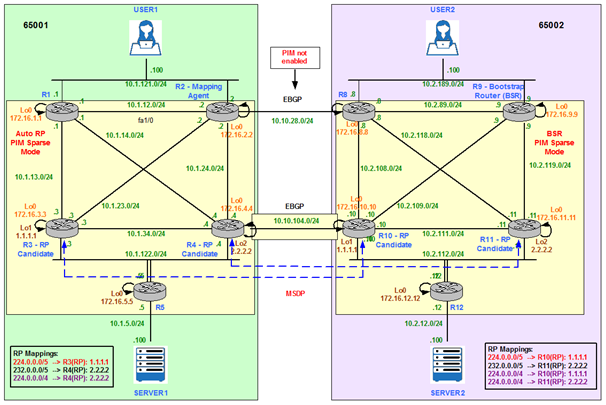
Figure 13
Figure 13 above shows that candidate RPs in AS65001 (R3 and R4) share the same IP addresses that candidate RPs in AS 65002 (R10 and R11):
- R3 and R10: 1.1.1.1/32
- R4 and R11: 2.2.2.2/32
This is known as Anycast RPs. Anycast RP is an implementation strategy that provides load sharing and redundancy in PIM SM networks. Anycast RP allows two or more RPs to share the load for Source Registration and the ability to act as hot backup routers for each other. MSDP is the key protocol that makes Anycast RP possible.
The Anycast RP loopback address should be configured with a 32-bit mask, making it a host address. All the downstream routers should be configured to “know” that the Anycast RP loopback address is the IP address of their local RP. In our topology Auto-RP is used to advertise the candidate RPs R3 (1.1.1.1/32) and R4 (2.2.2.2/32) in AS65001 and BSR is used to advertise the candidate RPs R10 (1.1.1.1/32) and R11 (2.2.2.2/32) in AS65002. IP routing automatically will select the topologically closest RP address (1.1.1.1/32 or 2.2.2.2/32) for each Source and Receiver.
Because a Source may register with one RP and Receivers may join to a different RP (e.g. User2 in AS65002 joins 224.1.1.1 and Server1 in AS65001 sends traffic to 224.1.1.1), a method is needed for the RPs (R3 and R10) to exchange information about active Sources. This information exchange is done with MSDP.
When a Source registers with one RP, an SA message will be sent to the other MSDP peers informing them that there is an active Source for a particular Multicast Group. The result is that each RP will know about the Active sources in the area of the other RPs. If any of the RPs were to fail, IP routing would converge and one of the RPs would become the active RP in more than one area. New Sources would register with the backup RP. Receivers would join toward the new RP and connectivity would be maintained.
Note that the RP is normally needed only to start new sessions with Sources and Receivers. The RP facilitates the SPT so that Sources and Receivers can directly establish a multicast data flow. If a multicast data flow is already directly established between a Source and the Receiver, then an RP failure will not affect that session. Anycast RP ensures that new sessions with Sources and Receivers can begin at any time.
Now we proceed with the configuration. Note that the IP addresses selected for the peering cannot be the Anycast IP Addresses (1.1.1.1/32 or 2.2.2.2/32). For example, R3 peers with R10’s Loopback0 (172.16.10.10/32) from its Loopback0 (172.16.1.1/32). R3 and R10’s Loopback1 (1.1.1.1/32, the Anycast address) cannot be used.
R3(config)# ip msdp peer 172.16.10.10 connect-source Loopback0 remote-as 65002
R4(config)#ip msdp peer 172.16.11.11 connect-source Loopback0 remote-as 65002
R10(config)#ip msdp peer 172.16.3.3 connect-source Loopback0 remote-as 65001
R11(config)#ip msdp peer 172.16.4.4 connect-source Loopback0 remote-as 65001
The output below shows the MSDP peering sessions have been successfully established.
R3#show ip msdp summary
MSDP Peer Status Summary
Peer Address AS State Uptime/ Reset SA Peer Name
Downtime Count Count
172.16.10.10 65002 Up 00:01:16 2 0 ?
MSDP Peer Status Summary
Peer Address AS State Uptime/ Reset SA Peer Name
Downtime Count Count
172.16.10.10 65002 Up 00:01:16 2 0 ?
R4#show ip msdp summary
MSDP Peer Status Summary
Peer Address AS State Uptime/ Reset SA Peer Name
Downtime Count Count
172.16.11.11 65002 Up 00:00:38 1 0 ?
MSDP Peer Status Summary
Peer Address AS State Uptime/ Reset SA Peer Name
Downtime Count Count
172.16.11.11 65002 Up 00:00:38 1 0 ?
R10#show ip msdp summary
MSDP Peer Status Summary
Peer Address AS State Uptime/ Reset SA Peer Name
Downtime Count Count
172.16.3.3 65001 Up 00:01:05 0 0 ?
MSDP Peer Status Summary
Peer Address AS State Uptime/ Reset SA Peer Name
Downtime Count Count
172.16.3.3 65001 Up 00:01:05 0 0 ?
R11#show ip msdp summary
MSDP Peer Status Summary
Peer Address AS State Uptime/ Reset SA Peer Name
Downtime Count Count
172.16.4.4 65001 Up 00:00:16 0 0 ?
MSDP Peer Status Summary
Peer Address AS State Uptime/ Reset SA Peer Name
Downtime Count Count
172.16.4.4 65001 Up 00:00:16 0 0 ?
Configuration Requirements
Our goal in this section is to achieve the following requirements:
- User1 receives Multicast traffic for 224.1.1.1 and 227.3.3.3 from Server1 and 234.2.2.2 from Server2.
- User2 receives Multicast traffic for 224.1.1.1 from Server1 and 234.2.2.2 and 227.3.3.3 from Server2.
- SERVER 1 sends Multicast traffic to 224.1.1.1, 227.3.3.3.
- SERVER 2 sends Multicast traffic to 234.2.2.2, 227.3.3.3.
- The ASs must never see any RP announcement from the other AS.
Server 1 send Multicast Traffic to 224.1.1.1
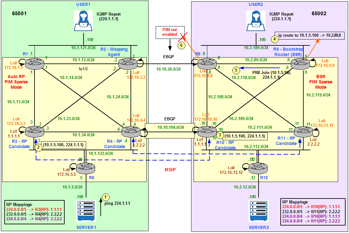
Figure 14
Server1 only receives replies to the pings from User1 (10.1.121.100) located in its local AS. This indicates there is a problem in the multicast design that is not allowing User2 to receive the Multicast flow.
SERVER1#ping 224.1.1.1 repeat 10000
Type escape sequence to abort.
Sending 10000, 100-byte ICMP Echos to 224.1.1.1, timeout is 2 seconds:
Type escape sequence to abort.
Sending 10000, 100-byte ICMP Echos to 224.1.1.1, timeout is 2 seconds:
Reply to request 0 from 10.1.121.100, 44 ms
Reply to request 1 from 10.1.121.100, 44 ms
Reply to request 2 from 10.1.121.100, 44 ms
Reply to request 3 from 10.1.121.100, 60 ms
Reply to request 4 from 10.1.121.100, 68 ms
[…]
We query R3 Multicast Routing Table for 224.1.1.1 and we see both (*,G) and (S,G) pairs as expected.
R3#show ip mroute 224.1.1.1
[…]
(*, 224.1.1.1), 00:00:37/00:03:04, RP 1.1.1.1, flags: S
Incoming interface: Null, RPF nbr 0.0.0.0
Outgoing interface list:
FastEthernet1/0, Forward/Sparse, 00:00:25/00:03:04
[…]
(*, 224.1.1.1), 00:00:37/00:03:04, RP 1.1.1.1, flags: S
Incoming interface: Null, RPF nbr 0.0.0.0
Outgoing interface list:
FastEthernet1/0, Forward/Sparse, 00:00:25/00:03:04
(10.1.5.100, 224.1.1.1), 00:00:37/00:02:22, flags: PTA
Incoming interface: FastEthernet0/0, RPF nbr 10.1.122.5
Outgoing interface list: Null
We query R10 Multicast Routing Table for 224.1.1.1 and we see the (S,G) = (10.1.5.100, 224.1.1.1) pair is received via MSDP peer. However, the incoming interface is fa1/0 towards R8 instead of fa2/1 towards R4. Fa2/1 is the PIM SM enabled link to send and receive Multicast traffic to/from AS65001 and therefore must be selected as the incoming interface. This points to some kind of configuration issue in the topology.
R10#show ip mroute 224.1.1.1
IP Multicast Routing Table
Flags: D – Dense, S – Sparse, B – Bidir Group, s – SSM Group, C – Connected,
L – Local, P – Pruned, R – RP-bit set, F – Register flag,
T – SPT-bit set, J – Join SPT, M – MSDP created entry,
X – Proxy Join Timer Running, A – Candidate for MSDP Advertisement,
U – URD, I – Received Source Specific Host Report,
Z – Multicast Tunnel, z – MDT-data group sender,
Y – Joined MDT-data group, y – Sending to MDT-data group
Outgoing interface flags: H – Hardware switched, A – Assert winner
Timers: Uptime/Expires
Interface state: Interface, Next-Hop or VCD, State/Mode(*, 224.1.1.1), 00:00:30/stopped, RP 1.1.1.1, flags: S
Incoming interface: Null, RPF nbr 0.0.0.0
Outgoing interface list:
FastEthernet2/0, Forward/Sparse, 00:00:30/00:02:59
(10.1.5.100, 224.1.1.1), 00:00:30/00:02:29, flags: M
Incoming interface: FastEthernet1/0, RPF nbr 10.2.111.11
Outgoing interface list:
FastEthernet2/0, Forward/Sparse, 00:00:30/00:02:59
The output below shows a Multicast Reverse Path Forwarding (RPF) failure: R9 does not have a Multicast route to the Source 10.1.5.100.
R9#show ip rpf 10.1.5.100
RPF information for ? (10.1.5.100) failed, no route exists
RPF information for ? (10.1.5.100) failed, no route exists
R9#mtrace 10.1.5.100
Type escape sequence to abort.
Mtrace from 10.1.5.100 to 10.2.89.9 via RPF
From source (?) to destination (?)
Querying full reverse path…
0 10.2.89.9
-1 10.2.89.9 PIM [10.1.5.0/24]
-2 10.2.89.8 None No route
The problem is R8 is the preferred exit point for AS65002; it has been configured with Local Preference 200. This means all unicast/multicast traffic will exit the AS through R8-R2 and this link has not been configured for PIM SM.
R9#show ip bgp 10.1.5.100
BGP routing table entry for 10.1.5.0/24, version 17
Paths: (1 available, best #1, table Default-IP-Routing-Table)
Flag: 0x820
Not advertised to any peer
65001
172.16.8.8 (metric 2) from 172.16.11.11 (172.16.11.11)
Origin incomplete, metric 30, localpref 200, valid, internal, best
Originator: 172.16.8.8, Cluster list: 172.16.11.11
Enable Multicast BGP (MBGP)
In order to overcome the design limitation of not enabling PIM SM on fa2/1 between R2 and R8, we need to look for another way to influence the routing decision for Multicast traffic. This method has to select R10 as the exit point for 65002 instead of R8. We can use a static Multicast route or Multicast BGP (MBGP). The latest is the one chosen in our design.
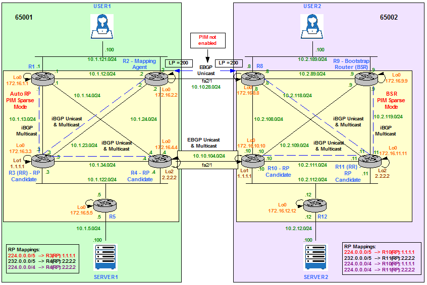
Figure 15
R3 is configured as Multicast Route Reflector (RR) for AS65001 and R11 is configured as Multicast Route Reflector (RR) for AS65002. R1, R2 and R4 are Multicast iBGP RR clients of R3 and R8, R9 and R10 are Multicast iBGP RR clients of R11. In addition, R4 and R10 are Multicast EBGP neighbors.
R1 configuration.
router bgp 65001
bgp router-id 172.16.1.1
no bgp default ipv4-unicast
neighbor 172.16.3.3 remote-as 65001
neighbor 172.16.3.3 update-source Loopback0
!
address-family ipv4 multicast
neighbor 172.16.3.3 activate
exit-address-family
bgp router-id 172.16.1.1
no bgp default ipv4-unicast
neighbor 172.16.3.3 remote-as 65001
neighbor 172.16.3.3 update-source Loopback0
!
address-family ipv4 multicast
neighbor 172.16.3.3 activate
exit-address-family
R2 configuration.
router bgp 65001
address-family ipv4 multicast
neighbor 172.16.3.3 activate
exit-address-family
address-family ipv4 multicast
neighbor 172.16.3.3 activate
exit-address-family
R4 configuration.
router bgp 65001
address-family ipv4 multicast
neighbor 10.10.104.10 activate
neighbor 172.16.3.3 activate
exit-address-family
address-family ipv4 multicast
neighbor 10.10.104.10 activate
neighbor 172.16.3.3 activate
exit-address-family
R3 configuration.
router bgp 65001
neighbor 172.16.1.1 peer-group IBGP_PEERS
address-family ipv4 multicast
neighbor IBGP_PEERS route-reflector-client
neighbor 172.16.1.1 activate
neighbor 172.16.2.2 activate
neighbor 172.16.4.4 activate
exit-address-family
neighbor 172.16.1.1 peer-group IBGP_PEERS
address-family ipv4 multicast
neighbor IBGP_PEERS route-reflector-client
neighbor 172.16.1.1 activate
neighbor 172.16.2.2 activate
neighbor 172.16.4.4 activate
exit-address-family
R8 configuration.
router bgp 65002
address-family ipv4 multicast
neighbor 172.16.11.11 activate
exit-address-family
address-family ipv4 multicast
neighbor 172.16.11.11 activate
exit-address-family
R9 configuration.
router bgp 65002
bgp router-id 172.16.9.9
no bgp default ipv4-unicast
neighbor 172.16.11.11 remote-as 65002
neighbor 172.16.11.11 update-source Loopback0
!
address-family ipv4 multicast
neighbor 172.16.11.11 activate
exit-address-family
bgp router-id 172.16.9.9
no bgp default ipv4-unicast
neighbor 172.16.11.11 remote-as 65002
neighbor 172.16.11.11 update-source Loopback0
!
address-family ipv4 multicast
neighbor 172.16.11.11 activate
exit-address-family
R10 configuration.
router bgp 65002
address-family ipv4 multicast
neighbor 10.10.104.4 activate
neighbor 172.16.11.11 activate
exit-address-family
address-family ipv4 multicast
neighbor 10.10.104.4 activate
neighbor 172.16.11.11 activate
exit-address-family
R11 configuration.
router bgp 65002
neighbor 172.16.9.9 peer-group IBGP_PEERS
address-family ipv4 multicast
neighbor IBGP_PEERS route-reflector-client
neighbor 172.16.8.8 activate
neighbor 172.16.9.9 activate
neighbor 172.16.10.10 activate
exit-address-family
neighbor 172.16.9.9 peer-group IBGP_PEERS
address-family ipv4 multicast
neighbor IBGP_PEERS route-reflector-client
neighbor 172.16.8.8 activate
neighbor 172.16.9.9 activate
neighbor 172.16.10.10 activate
exit-address-family
The output below shows that R3 is the Unicast and Multicast RR in AS65001.
R3#show bgp ipv4 unicast summary
[…]
Neighbor V AS MsgRcvd MsgSent TblVer InQ OutQ Up/Down State/PfxRcd
172.16.1.1 4 65001 4 5 0 0 0 00:00:17 (NoNeg)
172.16.2.2 4 65001 226 223 202 0 0 00:28:59 26
172.16.4.4 4 65001 223 224 202 0 0 00:29:01 25
[…]
Neighbor V AS MsgRcvd MsgSent TblVer InQ OutQ Up/Down State/PfxRcd
172.16.1.1 4 65001 4 5 0 0 0 00:00:17 (NoNeg)
172.16.2.2 4 65001 226 223 202 0 0 00:28:59 26
172.16.4.4 4 65001 223 224 202 0 0 00:29:01 25
R3#show bgp ipv4 multicast summary
[…]
Neighbor V AS MsgRcvd MsgSent TblVer InQ OutQ Up/Down State/PfxRcd
172.16.1.1 4 65001 4 5 7 0 0 00:00:39 0
172.16.2.2 4 65001 227 224 7 0 0 00:29:21 0
172.16.4.4 4 65001 223 224 7 0 0 00:29:24 0
On the other hand, R1 only runs the BGP Multicast address family.
R1#show bgp ipv4 unicast summary
R1#show bgp ipv4 multicast summary
[…]
Neighbor V AS MsgRcvd MsgSent TblVer InQ OutQ Up/Down State/PfxRcd
172.16.3.3 4 65001 6 5 2 0 0 00:01:23 0
R2 has R3 as Multicast iBGP neighbor, R3 as Unicast iBGP neighbor and R8 as Unicast EBGP neighbor.
R2#show bgp ipv4 unicast summary
[…]
Neighbor V AS MsgRcvd MsgSent TblVer InQ OutQ Up/Down State/PfxRcd
10.10.28.8 4 65002 139 151 132 0 0 00:01:17 18
172.16.3.3 4 65001 199 203 132 0 0 00:05:46 16
[…]
Neighbor V AS MsgRcvd MsgSent TblVer InQ OutQ Up/Down State/PfxRcd
10.10.28.8 4 65002 139 151 132 0 0 00:01:17 18
172.16.3.3 4 65001 199 203 132 0 0 00:05:46 16
R2#show bgp ipv4 multicast summary
[…]
Neighbor V AS MsgRcvd MsgSent TblVer InQ OutQ Up/Down State/PfxRcd
172.16.3.3 4 65001 199 203 4 0 0 00:05:53 0
Finally, R4 has R3 as Unicast and Multicast iBGP neighbor and R10 as Unicast and Multicast EBGP neighbor.
R4#show bgp ipv4 unicast summary
[…]
Neighbor V AS MsgRcvd MsgSent TblVer InQ OutQ Up/Down State/PfxRcd
10.10.104.10 4 65002 126 114 98 0 0 01:10:14 18
172.16.3.3 4 65001 200 199 98 0 0 00:06:39 14
[…]
Neighbor V AS MsgRcvd MsgSent TblVer InQ OutQ Up/Down State/PfxRcd
10.10.104.10 4 65002 126 114 98 0 0 01:10:14 18
172.16.3.3 4 65001 200 199 98 0 0 00:06:39 14
R4#show bgp ipv4 multicast summary
[…]Neighbor V AS MsgRcvd MsgSent TblVer InQ OutQ Up/Down State/PfxRcd
10.10.104.10 4 65002 126 114 3 0 0 01:10:19 0
172.16.3.3 4 65001 200 199 3 0 0 00:06:44 0
However, if we recheck multicast reachibility to the source 10.1.5.100 from R9 we can see that there is not route available yet.
R9#show ip rpf 10.1.5.100
RPF information for ? (10.1.5.100) failed, no route exists
RPF information for ? (10.1.5.100) failed, no route exists
R9#mtrace 10.1.5.100
Type escape sequence to abort.
Mtrace from 10.1.5.100 to 10.2.89.9 via RPF
From source (?) to destination (?)
Querying full reverse path…
0 10.2.89.9
-1 10.2.89.9 None No route
To resolve the RPF check failure, we need to advertise the Multicast Source address (or network 10.1.5.0/24) into MBGP as shown in Figure 16. Remember the order of preference:
- Static IP Multicast route (ip mroute command).
- MBGP Multicast route.
- Unicast Route.
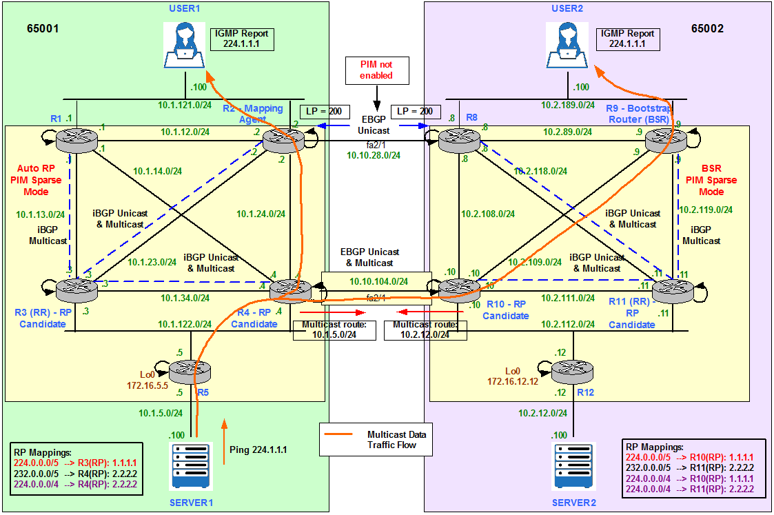
Figure 16
R4 advertises 10.1.5.0/24 network into MBGP.
R4(config)#router bgp 65001
R4(config-router)# address-family ipv4 multicast
R4(config-router-af)#network 10.1.5.0 mask 255.255.255.0
R4(config-router)# address-family ipv4 multicast
R4(config-router-af)#network 10.1.5.0 mask 255.255.255.0
R9 now knows about a Multicast route to Server1 (Source) that is preferred over any unicast route.
R9#show bgp ipv4 multicast
BGP table version is 2, local router ID is 172.16.9.9
Status codes: s suppressed, d damped, h history, * valid, > best, i – internal,
r RIB-failure, S Stale
Origin codes: i – IGP, e – EGP, ? – incomplete Network Next Hop Metric LocPrf Weight Path
*>i10.1.5.0/24 10.10.104.4 20 100 0 65001 i
BGP table version is 2, local router ID is 172.16.9.9
Status codes: s suppressed, d damped, h history, * valid, > best, i – internal,
r RIB-failure, S Stale
Origin codes: i – IGP, e – EGP, ? – incomplete Network Next Hop Metric LocPrf Weight Path
*>i10.1.5.0/24 10.10.104.4 20 100 0 65001 i
R9#mtrace 10.1.5.100
Type escape sequence to abort.
Mtrace from 10.1.5.100 to 10.2.89.9 via RPF
From source (?) to destination (?)
Querying full reverse path…
0 10.2.89.9
-1 10.2.89.9 PIM/MBGP [10.1.5.0/24]
-2 10.2.109.10 PIM/MBGP [10.1.5.0/24]
-3 10.10.104.4 PIM [10.1.5.0/24]
-4 10.1.122.5 PIM [10.1.5.0/24]
-5 10.1.5.100
R9#show ip mroute 224.1.1.1
[…]
(*, 224.1.1.1), 01:59:01/stopped, RP 1.1.1.1, flags: SJC
Incoming interface: FastEthernet2/0, RPF nbr 10.2.109.10
Outgoing interface list:
FastEthernet0/0, Forward/Sparse, 01:59:01/00:02:04
(10.1.5.100, 224.1.1.1), 00:12:26/00:02:36, flags: JT
Incoming interface: FastEthernet2/0, RPF nbr 10.2.109.10, Mbgp
Outgoing interface list:
FastEthernet0/0, Forward/Sparse, 00:12:26/00:02:04
Finally, if we now ping from Server1 to the Multicast Group 224.1.1.1 we can see that User1 and User2 are both responding.
SERVER1#ping 224.1.1.1 repeat 2
Type escape sequence to abort.
Sending 2, 100-byte ICMP Echos to 224.1.1.1, timeout is 2 seconds:
Reply to request 0 from 10.1.121.100, 32 ms
Reply to request 0 from 10.2.189.100, 560 ms
Reply to request 1 from 10.1.121.100, 44 ms
Reply to request 1 from 10.2.189.100, 876 ms
Type escape sequence to abort.
Sending 2, 100-byte ICMP Echos to 224.1.1.1, timeout is 2 seconds:
Reply to request 0 from 10.1.121.100, 32 ms
Reply to request 0 from 10.2.189.100, 560 ms
Reply to request 1 from 10.1.121.100, 44 ms
Reply to request 1 from 10.2.189.100, 876 ms
Server 2 sends Multicast Traffic to 234.2.2.2
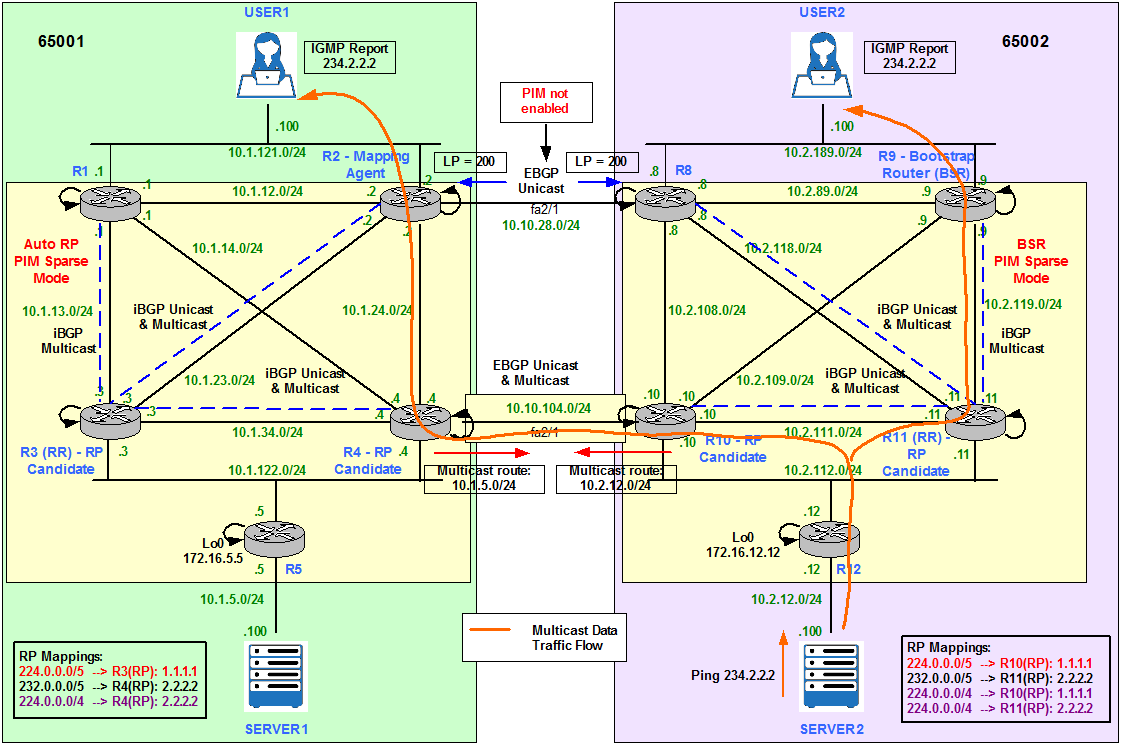
Figure 17
As we saw in the previous section, we need to advertise the Source IP address (Server2) or network (10.1.12.0/24) for User1 to be able to receive the Multicast traffic.
R10(config)#router bgp 65001
R10(config-router)# address-family ipv4 multicast
R10(config-router-af)#network 10.2.12.0 mask 255.255.255.0
R10(config-router)# address-family ipv4 multicast
R10(config-router-af)#network 10.2.12.0 mask 255.255.255.0
If we run a ping to 234.2.2.2 from Server2, both User1 and User2 are responding.
SERVER2#ping 234.2.2.2 repeat 2
Type escape sequence to abort.
Sending 2, 100-byte ICMP Echos to 234.2.2.2, timeout is 2 seconds:
Type escape sequence to abort.
Sending 2, 100-byte ICMP Echos to 234.2.2.2, timeout is 2 seconds:
Reply to request 0 from 10.1.121.100, 44 ms
Reply to request 0 from 10.2.189.100, 64 ms
Reply to request 1 from 10.1.121.100, 60 ms
Reply to request 1 from 10.2.189.100, 72 ms
R2 shows the interface Fa0/1 towards R4 as the incoming interface for (10.2.12.100, 234.2.2.2).
R2#show ip mroute 234.2.2.2
[…]
(*, 234.2.2.2), 03:12:09/stopped, RP 2.2.2.2, flags: SJC
Incoming interface: FastEthernet0/1, RPF nbr 10.1.24.4
Outgoing interface list:
FastEthernet0/0, Forward/Sparse, 03:12:09/00:01:54
[…]
(*, 234.2.2.2), 03:12:09/stopped, RP 2.2.2.2, flags: SJC
Incoming interface: FastEthernet0/1, RPF nbr 10.1.24.4
Outgoing interface list:
FastEthernet0/0, Forward/Sparse, 03:12:09/00:01:54
(10.2.12.100, 234.2.2.2), 00:00:50/00:02:29, flags: JT
Incoming interface: FastEthernet0/1, RPF nbr 10.1.24.4, Mbgp
Outgoing interface list:
FastEthernet0/0, Forward/Sparse, 00:00:50/00:02:09
The mtrace command verifies the reverse path from R2 to the Multicast Source Server2.
R2#mtrace 10.2.12.100
Type escape sequence to abort.
Mtrace from 10.2.12.100 to 10.1.24.2 via RPF
From source (?) to destination (?)
Querying full reverse path…
0 10.1.24.2
-1 10.1.24.2 PIM/MBGP [10.2.12.0/24]
-2 10.1.24.4 PIM/MBGP [10.2.12.0/24]
-3 10.10.104.10 PIM [10.2.12.0/24]
-4 10.2.112.12 PIM [10.2.12.0/24]
-5 10.2.12.100
We can see the Unicast traffic goes through R8 though.
R2#traceroute 10.2.12.100
Type escape sequence to abort.
Tracing the route to 10.2.12.100
1 10.10.28.8 1072 msec 952 msec 408 msec
2 10.2.118.11 [AS 65002] 452 msec 1132 msec *
3 10.2.112.12 [AS 65002] 1212 msec 808 msec 320 msec
4 10.2.12.100 [AS 65002] 132 msec 1184 msec 284 msec
Type escape sequence to abort.
Tracing the route to 10.2.12.100
1 10.10.28.8 1072 msec 952 msec 408 msec
2 10.2.118.11 [AS 65002] 452 msec 1132 msec *
3 10.2.112.12 [AS 65002] 1212 msec 808 msec 320 msec
4 10.2.12.100 [AS 65002] 132 msec 1184 msec 284 msec
Server 1 and Server 2 send Multicast Traffic to 227.3.3.3 – MSDP SA Filtering
The next Multicast requirement says:
- SERVER 1 sends Multicast traffic to 227.3.3.3 and it is only received by User1.
- SERVER 2 sends Multicast traffic to 227.3.3.3 and it is only received by User2.
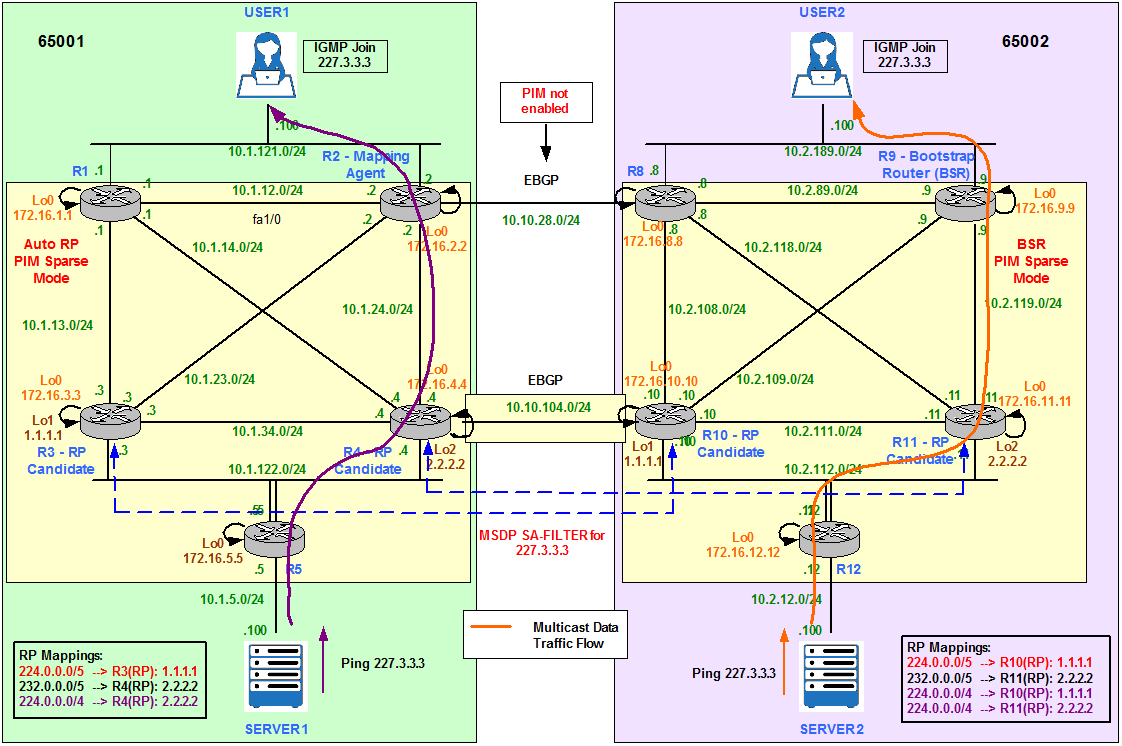
Figure 18
MSDP-SA messages contain (S,G) information for RPs (called MSDP peers) in PIM SM domains. This mechanism allows RPs to learn about Multicast Sources in remote PIM SM domains so that they can join those Sources if there are local Receivers in their own domain. With a default configuration, MSDP exchanges SA messages without filtering them for specific Source or Group addresses.
Typically, there are a number of (S,G) states in a PIM SM domain that should stay within the PIM SM domain, but, due to default filtering, they get passed in SA messages to MSDP peers. In the native IP Multicast Internet, this default leads to excessive (S,G) information being shared. To improve the scalability of MSDP in the native IP Multicast Internet, and to avoid global visibility of domain local (S,G) information, it is recommended to use SA filtering.
Coming back to our scenario (Figure 18), we need to filter Group 227.3.3.3 from being advertised to MSDP peers. Therefore, only local Receivers will receive the Multicast traffic for the local Source.
User1 and User 2 join the Multicast Group 227.3.3.3.
interface Fastethernet0/0
ip igmp join-group 227.3.3.3
ip igmp join-group 227.3.3.3
Before configuring any MSDP Filtering we can see User2 in AS65002 is responding to the pings from Server1 in AS65001. This is not the desired output, we want only User1 to receive the Multicast traffic from Server1.
SERVER1#ping 227.3.3.3 repeat 2
Type escape sequence to abort.
Sending 2, 100-byte ICMP Echos to 227.3.3.3, timeout is 2 seconds:
Type escape sequence to abort.
Sending 2, 100-byte ICMP Echos to 227.3.3.3, timeout is 2 seconds:
Reply to request 0 from 10.1.121.100, 68 ms
Reply to request 0 from 10.2.189.100, 736 ms
Reply to request 1 from 10.1.121.100, 84 ms
Reply to request 1 from 10.2.189.100, 268 ms
Reply to request 1 from 10.1.121.100, 96 ms
R3 configuration.
access-list 111 deny ip any host 227.3.3.3
access-list 111 permit ip any any
access-list 111 permit ip any any
ip msdp sa-filter in 172.16.10.10 list 111
ip msdp sa-filter out 172.16.10.10 list 111
R4 configuration.
access-list 111 deny ip any host 227.3.3.3
access-list 111 permit ip any any
access-list 111 permit ip any any
ip msdp sa-filter in 172.16.11.11 list 111
ip msdp sa-filter out 172.16.11.11 list 111
R10 configuration.
access-list 111 deny ip any host 227.3.3.3
access-list 111 permit ip any any
access-list 111 permit ip any any
ip msdp sa-filter in 172.16.3.3 list 111
ip msdp sa-filter out 172.16.3.3 list 111
R11 configuration.
access-list 111 deny ip any host 227.3.3.3
access-list 111 permit ip any any
access-list 111 permit ip any any
ip msdp sa-filter in 172.16.4.4 list 111
ip msdp sa-filter out 172.16.4.4 list 111
If we check the MSDP Peer information, we can see the filter has been applied inbound and outbound.
R3#show ip msdp peer
MSDP Peer 172.16.10.10 (?), AS 65002 (configured AS)
Connection status:
State: Up, Resets: 2, Connection source: Loopback0 (172.16.3.3)
Uptime(Downtime): 02:10:49, Messages sent/received: 138/131
Output messages discarded: 0
Connection and counters cleared 04:05:51 ago
SA Filtering:
Input (S,G) filter: 111, route-map: none
Input RP filter: none, route-map: none
Output (S,G) filter: 111, route-map: none
Output RP filter: none, route-map: none
SA-Requests:
Input filter: none
Peer ttl threshold: 0
SAs learned from this peer: 0
Input queue size: 0, Output queue size: 0
Message counters:
RPF Failure count: 0
SA Messages in/out: 0/34
SA Requests in: 0
SA Responses out: 0
Data Packets in/out: 0/3
We run the same ping on Server1 and this time only User1 answers.
SERVER1#ping 227.3.3.3 repeat 5
Type escape sequence to abort.
Sending 5, 100-byte ICMP Echos to 227.3.3.3, timeout is 2 seconds:
Reply to request 0 from 10.1.121.100, 32 ms
Reply to request 1 from 10.1.121.100, 68 ms
Reply to request 2 from 10.1.121.100, 60 ms
Reply to request 3 from 10.1.121.100, 88 ms
Reply to request 4 from 10.1.121.100, 60 ms
We ping 227.3.3.3 from Server2 and only User2 answers.
SERVER2#ping 227.3.3.3 repeat 5
Type escape sequence to abort.
Sending 5, 100-byte ICMP Echos to 227.3.3.3, timeout is 2 seconds:
Reply to request 0 from 10.2.189.100, 1176 ms
Reply to request 1 from 10.2.189.100, 60 ms
Reply to request 1 from 10.2.189.100, 76 ms
Reply to request 2 from 10.2.189.100, 80 ms
Reply to request 3 from 10.2.189.100, 60 ms
Reply to request 4 from 10.2.189.100, 52 ms
Appendix
Filter RP-Group in the Mapping Agent
R3 and R4 are configured to advertise themselves as candidate RPs for 227.3.3.3.
R3 configuration.
ip access-list standard MULTICAST_GROUPS
permit 227.3.3.3
permit 224.0.0.0 7.255.255.255
permit 224.0.0.0 15.255.255.255
permit 227.3.3.3
permit 224.0.0.0 7.255.255.255
permit 224.0.0.0 15.255.255.255
ip pim send-rp-announce Loopback1 scope 100 group-list MULTICAST_GROUPS
R4 configuration.
ip access-list standard MULTICAST_GROUPS
permit 227.3.3.3
permit 232.0.0.0 7.255.255.255
permit 224.0.0.0 15.255.255.255
permit 227.3.3.3
permit 232.0.0.0 7.255.255.255
permit 224.0.0.0 15.255.255.255
ip pim send-rp-announce Loopback1 scope 100 group-list MULTICAST_GROUPS
R2, the MA, receives the RP announcements and updates the RP-to-Group mappings.
R2(config)#do show ip pim rp map
PIM Group-to-RP Mappings
This system is an RP-mapping agent (Loopback0)Group(s) 224.0.0.0/5
RP 1.1.1.1 (?), v2v1
Info source: 1.1.1.1 (?), elected via Auto-RP
Uptime: 00:00:23, expires: 00:02:32
Group(s) 224.0.0.0/4
RP 2.2.2.2 (?), v2v1
Info source: 2.2.2.2 (?), elected via Auto-RP
Uptime: 00:00:04, expires: 00:02:53
RP 1.1.1.1 (?), v2v1
Info source: 1.1.1.1 (?), via Auto-RP
Uptime: 00:00:23, expires: 00:02:36
Group(s) 227.3.3.3/32
RP 2.2.2.2 (?), v2v1
Info source: 2.2.2.2 (?), elected via Auto-RP
Uptime: 00:00:04, expires: 00:02:52
RP 1.1.1.1 (?), v2v1
Info source: 1.1.1.1 (?), via Auto-RP
Uptime: 00:00:23, expires: 00:02:36
Group(s) 232.0.0.0/5
RP 2.2.2.2 (?), v2v1
Info source: 2.2.2.2 (?), elected via Auto-RP
Uptime: 00:00:04, expires: 00:02:53
Now imagine we do not want R3 to be a candidate RP for 227.3.3.3. We can do the configuration on R3 accordingly or we can filter on the MA, R2. The first option is recommended but if R3 is not managed by us or it is a Rogue RP, we can use the second option as a Control Plane Security feature. Mainly this avoids non authorized RPs to announce themselves as legitimate RPs. It is not recommended to be used as a filter of what RPs serve what Groups.
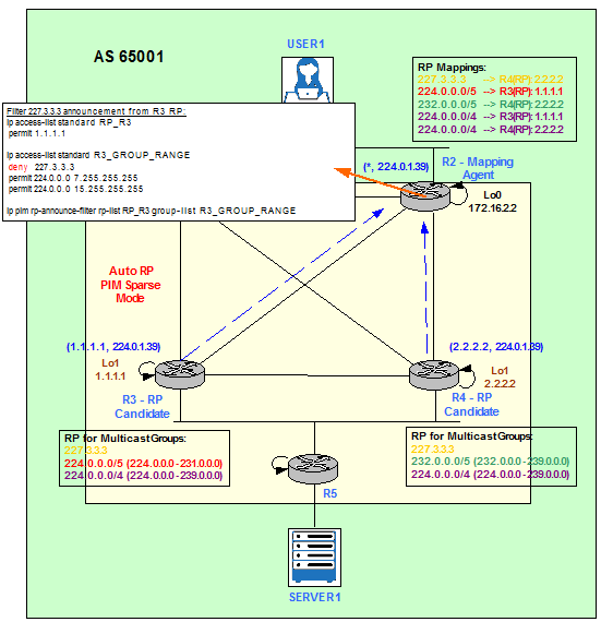
Figure 19
Match RPs.
ip access-list standard RP_R3
permit 1.1.1.1
ip access-list standard RP_R4
permit 2.2.2.2
ip access-list standard ALL_OTHER_RPS
deny 1.1.1.1
deny 2.2.2.2
permit any
permit 1.1.1.1
ip access-list standard RP_R4
permit 2.2.2.2
ip access-list standard ALL_OTHER_RPS
deny 1.1.1.1
deny 2.2.2.2
permit any
Match Multicast Groups.
ip access-list standard R3_GROUP_RANGE
deny 227.3.3.3
permit 224.0.0.0 7.255.255.255
permit 224.0.0.0 15.255.255.255
ip access-list standard R4_GROUP_RANGE
permit 227.3.3.3
permit 232.0.0.0 7.255.255.255
permit 224.0.0.0 15.255.255.255
ip access-list standard ALL_OTHER_GROUP_RANGES
deny 224.0.0.0 15.255.255.255
deny 227.3.3.3
permit 224.0.0.0 7.255.255.255
permit 224.0.0.0 15.255.255.255
ip access-list standard R4_GROUP_RANGE
permit 227.3.3.3
permit 232.0.0.0 7.255.255.255
permit 224.0.0.0 15.255.255.255
ip access-list standard ALL_OTHER_GROUP_RANGES
deny 224.0.0.0 15.255.255.255
Apply the filters on R2, the MA.
ip pim rp-announce-filter rp-list RP_R3 group-list R3_GROUP_RANGE
ip pim rp-announce-filter rp-list RP_R4 group-list R4_GROUP_RANGE
ip pim rp-announce-filter rp-list ALL_OTHER_RPS group-list ALL_OTHER_GROUP_RANGES
ip pim rp-announce-filter rp-list RP_R4 group-list R4_GROUP_RANGE
ip pim rp-announce-filter rp-list ALL_OTHER_RPS group-list ALL_OTHER_GROUP_RANGES
This filter only works if R3 advertises and R2 matches exactly the same Multicast Group.
R2 configuration.
ip access-list standard R3_GROUP_RANGE
deny 227.3.3.3
permit 224.0.0.0 7.255.255.255
permit 224.0.0.0 15.255.255.255
deny 227.3.3.3
permit 224.0.0.0 7.255.255.255
permit 224.0.0.0 15.255.255.255
R3 configuration.
ip access-list standard MULTICAST_GROUPS
permit 227.3.3.3
permit 224.0.0.0 7.255.255.255
permit 224.0.0.0 15.255.255.255
permit 227.3.3.3
permit 224.0.0.0 7.255.255.255
permit 224.0.0.0 15.255.255.255
If we now check the RP-to-Group mappings we can see R3 (1.1.1.1) is not longer available for 227.3.3.3.
R2#
*Dec 5 07:30:11.329: Auto-RP(0): Received RP-announce packet of length 48, from 1.1.1.1, RP_cnt 1, ht 181
*Dec 5 07:30:11.329: Auto-RP(0): Filtered 227.3.3.3/32 for RP 1.1.1.1
R2#show ip pim rp map
PIM Group-to-RP Mappings
This system is an RP-mapping agent (Loopback0)Group(s) 224.0.0.0/5
RP 1.1.1.1 (?), v2v1
Info source: 1.1.1.1 (?), elected via Auto-RP
Uptime: 00:01:03, expires: 00:02:54
Group(s) 224.0.0.0/4
RP 2.2.2.2 (?), v2v1
Info source: 2.2.2.2 (?), elected via Auto-RP
Uptime: 00:00:43, expires: 00:02:15
RP 1.1.1.1 (?), v2v1
Info source: 1.1.1.1 (?), via Auto-RP
Uptime: 00:00:03, expires: 00:02:57
Group(s) 227.3.3.3/32
RP 2.2.2.2 (?), v2v1
Info source: 2.2.2.2 (?), elected via Auto-RP
Uptime: 00:00:43, expires: 00:02:16
Group(s) 232.0.0.0/5
RP 2.2.2.2 (?), v2v1
Info source: 2.2.2.2 (?), elected via Auto-RP
Uptime: 00:00:43, expires: 00:02:12
Filter RP Announcements and Mappings to leave the AS
Figure 20 shows a capture run between R4 and R10. It shows RP announcements on 224.0.1.39 and RP mappings on 224.0.1.40 being advertised on fa2/1.
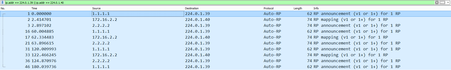
Figure 20
We can filter them with the following configuration on R4 and R10.
access-list 10 deny 224.0.1.39
access-list 10 deny 224.0.1.40
access-list 10 permit any
access-list 10 deny 224.0.1.40
access-list 10 permit any
interface FastEthernet2/1
ip multicast boundary 10
Now the same capture does not show any packets.

Figure 21
On R10 the same result can be achieved by issuing the ip pim bsr-border interface command:
interface FastEthernet2/1
ip pim bsr-border
ip pim bsr-border
ip pim accept-register (S,G)
To configure a RP to filter PIM Register messages. Use this command to prevent unauthorized Sources from registering with the RP.
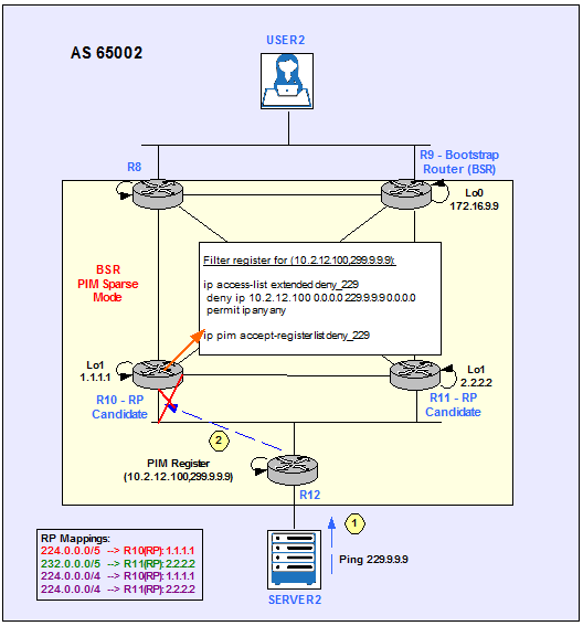
Figure 22
The following example shows how to deny Register packets from Server2 to the Multicast Group 229.9.9.9. All other PIM register messages not matching the extended access list are permitted.
R10 configuration.
ip access-list extended deny_229
deny ip 10.2.12.100 0.0.0.0 229.9.9.9 0.0.0.0
permit ip any any
deny ip 10.2.12.100 0.0.0.0 229.9.9.9 0.0.0.0
permit ip any any
ip pim accept-register list deny_229
SERVER2#ping 229.9.9.9 repeat 100
Type escape sequence to abort.
Sending 100, 100-byte ICMP Echos to 229.9.9.9, timeout is 2 seconds:
……
Type escape sequence to abort.
Sending 100, 100-byte ICMP Echos to 229.9.9.9, timeout is 2 seconds:
……
R10#
*Mar 1 00:26:21.947: %PIM-4-INVALID_SRC_REG: Received Register from 10.2.112.12 for (10.2.12.100, 229.9.9.9), not willing to be RP
*Mar 1 00:26:21.947: %PIM-4-INVALID_SRC_REG: Received Register from 10.2.112.12 for (10.2.12.100, 229.9.9.9), not willing to be RP
R10#show ip pim rp 229.9.9.9
Group 229.9.9.9 not found
We can disable the filter with the no command.
R10(config)#no ip pim accept-register list deny_229
R10#show ip pim rp 229.9.9.9
Group: 229.9.9.9, RP: 1.1.1.1, v2, next RP-reachable in 00:01:27
ip pim accept-rp (*,G)
To configure a router to accept join or prune messages destined for a specified RP and for a specific list of Groups, use the ip pim accept-rp command in global configuration mode.
This command causes the router to accept only (*, G) join messages destined for the specified RP address. Additionally, the Group address must be in the range specified by the access list.
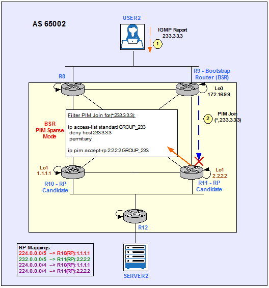
Figure 23
The following example shows how to configure R11 to deny join or prune messages destined for the RP at address 2.2.2.2 for the Multicast Group 233.3.3.3:
R11(config)#ip access-list standard GROUP_233
R11(config-std-nacl)#deny host 233.3.3.3
R11(config-std-nacl)#permit any
R11(config)#ip pim accept-rp 2.2.2.2 GROUP_233
R11(config-std-nacl)#deny host 233.3.3.3
R11(config-std-nacl)#permit any
R11(config)#ip pim accept-rp 2.2.2.2 GROUP_233
User2 now joins 233.3.3.3.
USER2(config)#interface FastEthernet0/0
USER2(config-if)#ip igmp join-group 233.3.3.3
USER2(config-if)#ip igmp join-group 233.3.3.3
R11#
*Mar 1 00:35:54.079: %PIM-6-INVALID_RP_JOIN: Received (*, 233.3.3.3) Join from 10.2.111.10 for invalid RP 2.2.2.2
R11#show ip pim rp 233.3.3.3
Group 233.3.3.3 not found
We can disable the filter with the no command.
R11(config)#no ip pim accept-rp 2.2.2.2 GROUP_233
R11#show ip pim rp 233.3.3.3
Group: 233.3.3.3, RP: 2.2.2.2, v2, next RP-reachable in 00:01:27
Multicast Stub Routing
Multicast Stub routing can be used for remote sites that are connected to the main site using low bandwidth links. The remote router has to accept RP discovery messages, build the RP cache and maintain states in the multicast routing table for all its local Receivers.
When we configure a router as Multicast Stub then it will not process any PIM or IGMP messages. Instead it will forward all these messages to the router on the main site.
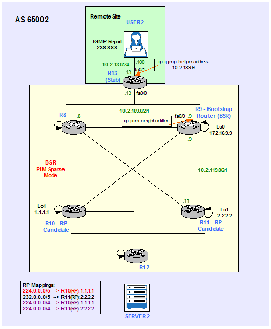
Figure 24
R13 simulates the remote site in our configuration example.
interface FastEthernet0/1
ip pim sparse-mode
ip igmp helper-address 10.2.189.9
ip pim sparse-mode
ip igmp helper-address 10.2.189.9
R9 is the router that connects R13 to the main site.
access-list 13 deny host 10.2.189.13
access-list 13 permit any
access-list 13 permit any
interface FastEthernet0/0
ip pim sparse-mode
ip pim neighbor-filter 13
The result of this configuration is that R9 appears as it would have the Receivers directly connected to its fa0/0. It takes the role of R13.
R9#show ip igmp groups
IGMP Connected Group Membership
Group Address Interface Uptime Expires Last Reporter Group Accounted
238.8.8.8 FastEthernet0/0 00:07:43 00:02:16 10.2.189.13
224.0.1.40 FastEthernet0/0 01:54:51 00:02:19 10.2.189.13
224.0.1.40 Loopback0 01:54:54 00:02:13 172.16.9.9
IGMP Connected Group Membership
Group Address Interface Uptime Expires Last Reporter Group Accounted
238.8.8.8 FastEthernet0/0 00:07:43 00:02:16 10.2.189.13
224.0.1.40 FastEthernet0/0 01:54:51 00:02:19 10.2.189.13
224.0.1.40 Loopback0 01:54:54 00:02:13 172.16.9.9
We can verify that reachibility is maintened to the Receiver (User2) from the Source (Server2).
SERVER2#ping 238.8.8.8 repeat 5
Type escape sequence to abort.
Sending 5, 100-byte ICMP Echos to 238.8.8.8, timeout is 2 seconds:
Reply to request 0 from 10.2.13.15, 52 ms
Reply to request 1 from 10.2.13.15, 76 ms
Reply to request 2 from 10.2.13.15, 52 ms
Reply to request 3 from 10.2.13.15, 76 ms
Reply to request 4 from 10.2.13.15, 52 ms
References
https://www.cisco.com/c/en/us/support/docs/ip/multicast/118405-config-rp-00.html
http://www.routerfreak.com/pim-assert-mechanism/
https://www.cisco.com/c/en/us/td/docs/ios/solutions_docs/ip_multicast/Phase_1/mcstmsdp/mcst_p1.html
https://www.cisco.com/c/en/us/td/docs/ios/solutions_docs/ip_multicast/White_papers/anycast.html
https://www.cisco.com/c/en/us/support/docs/ip/ip-multicast/13717-49.html#topic1