NAT: IPsec DMVPN and Internet Access – Review NAT Deployment scenarios
This post describes different deployment scenarios where Network Address Translation (NAT) is implemented with IPsec DMVPN.
Contents
- Network Topology
- Network Address Translation (NAT) Overview
- What is Inside and Outside?
- NAT and Routing – Order of Operations
- Initial Configuration
- Scenario 1 – PAT, IPsec DMVPN and Internet Access
- Scenario 2 – Basic Static NAT Translation
- Scenario 3 – Server TCP Load Balancing
- Scenario 4 – Route-map Reversible
- Scenario 5 – Static Policy NAT
- Scenario 6 – Outside NAT and Add-route
- Scenario 7 – Static Extendable NAT and IP Aliasing
- References
Network Topology
Figure 1
Network Address Translation (NAT) Overview
Network Address Translation (NAT) translates non-routable private IP addresses to routable public IP addresses from a pool of public IP addresses that have been designated for NAT. This enables to conserve on the number of public IP addresses and implicitly enforces security hiding private IP addresses. NAT can also resolve overlapping subnet issues and it is widely deployed to connect devices to the Internet.
What is Inside and Outside?
Inside or Outside NAT addresses depend on where the device doing the translation is located in the network. It is easier to use an example in order to understand this terminology.
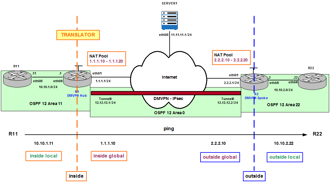
Figure 2
Figure 2 shows R1 is configured to be the Translator in the network and from its perspective we analyze a Ping from R11 to 2.2.2.10. The traffic flow is originated by R11’s eth0/0 IP address, 10.10.1.11. 10.10.1.11 is the Inside local IP address; private IP address before translation occurs. R1 translates the Inside local to an Inside global IP address from the NAT Pool. In this case the first available IP address is 1.1.1.10. 1.1.1.10 is the Inside public and routable IP address after translation. R2 receives the Ping because 2.2.2.10 is part of its local NAT Pool of public IP addresses. 2.2.2.10 is called Outside global IP address from R1’s perspective. R2 checks its NAT Translation database and finds out there is an entry that correlates 2.2.2.10 to R22’s eth0/0 IP address, 10.10.2.22. Therefore, R2 modifies the destination of the packet to be 10.10.2.22 and forwards the packet to the final destination. 10.10.2.22 is the Outside local IP address; a private external IP address after translation. In this scenario we have what is called double NAT (R1 and R2 are configured for NAT).
However, if the ping from R11 were destined to Server1 in the topology, Outside global and Outside local would have been the same IP address, 11.11.11.1. This is because Server1 is not doing NAT or it is not behind a device doing NAT. Inside local: 10.10.1.11, Inside global: 1.1.1.10 (or any other IP from R1’s NAT Pool), Outside global: 11.11.11.1 and Outside local: 11.11.11.1.
Figure 3 shows the same topology but in this case R2 is the Translator because the Ping is originated by R22 and destined to 1.1.1.11. The Inside local IP address is now R22’s eth0/0 IP address, 10.10.2.22, which is translated to an Inside global IP address from R2’s NAT Pool, for example, 2.2.2.11. R1 receives the Ping to 1.1.1.11, the Outside global, because it is part of its NAT Pool that is finally translated to the Outside local 10.10.1.11.
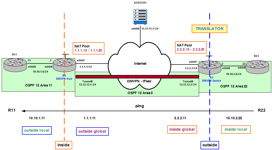
Figure 3
Note that in both scenarios the Ping is destined to an Outside global IP address because they are public and routable. It is not possible to ping directly to an Outside local IP address with double NAT configured because Outside local IP addresses are private and not routable. This is different when we ping Server1 because translation only happens once and Outside global and Outside local are the same public and routable IP address (11.11.11.1).
NAT and Routing – Order of Operations
On the Inside zone: Packets are first routed and then translated.
R1 in Figure 2 checks its routing table for the destination 2.2.2.10. R1 sees it needs to send the packet through eth0/1 to reach the destination, which happens to be configured for NAT. Once R1 knows the route to the destination it translates 10.10.1.11 to 1.1.1.10.
On the Outside zone: Packets are first translated and then routed which allows routing for returning packets with translated sources.
R2 receives the ping from R1. R2 sees the destination 2.2.2.10 is part of its NAT pool and needs to do the translation first in order to find out the final internal destination. 2.2.2.10 is translated to 10.10.2.22. R2 queries the routing table for destination 10.10.2.22 and finds out it needs to forward the packet through its eth0/0 interface.
Note- for NAT Virtual Interface (NVI) translation rules (NAT) are applied always after the route decision for Inside and Outside zones.
Initial Configuration

Figure 4
This is the initial configuration for Routing, Dynamic Multipoint VPN (DMVPN) and Internet Protocol Security (IPsec) Encapsulating Security Payload (ESP).
R1 Configuration:
router ospf 12
router-id 111.111.111.111
default-information originate always
router-id 111.111.111.111
default-information originate always
router bgp 65001
bgp router-id 1.1.1.1
bgp log-neighbor-changes
network 111.111.111.111 mask 255.255.255.255
neighbor 2.2.2.1 remote-as 65002
neighbor 2.2.2.1 ebgp-multihop 10
crypto isakmp policy 10
encr 3des
hash sha256
authentication pre-share
group 14
crypto isakmp key duconet address 222.222.222.222
crypto ipsec transform-set ESP-AES-MD5 esp-aes esp-md5-hmac
mode transport
crypto ipsec profile IPSEC_PROFILE
set transform-set ESP-AES-MD5
interface Tunnel0
ip address 12.12.12.1 255.255.255.0
no ip redirects
ip nhrp authentication duconet
ip nhrp map multicast dynamic
ip nhrp network-id 12
ip ospf network point-to-multipoint
ip ospf 12 area 0
tunnel source Loopback0
tunnel mode gre multipoint
tunnel key 12
tunnel protection ipsec profile IPSEC_PROFILE
interface Loopback0
ip address 111.111.111.111 255.255.255.255
interface Ethernet0/0
ip address 10.10.1.1 255.255.255.0
ip ospf 12 area 11
interface Ethernet0/1
ip address 1.1.1.1 255.255.255.0
R2 Configuration:
router ospf 12
router-id 222.222.222.222
default-information originate always
router-id 222.222.222.222
default-information originate always
router bgp 65002
bgp router-id 2.2.2.2
bgp log-neighbor-changes
network 222.222.222.222 mask 255.255.255.255
neighbor 1.1.1.1 remote-as 65001
neighbor 1.1.1.1 ebgp-multihop 10
crypto isakmp policy 10
encr 3des
hash sha256
authentication pre-share
group 14
crypto isakmp key duconet address 111.111.111.111
crypto ipsec transform-set ESP-AES-MD5 esp-aes esp-md5-hmac
mode transport
crypto ipsec profile IPSEC_PROFILE
set transform-set ESP-AES-MD5
interface Tunnel0
ip address 12.12.12.2 255.255.255.0
no ip redirects
ip nhrp authentication duconet
ip nhrp map 12.12.12.1 111.111.111.111
ip nhrp map multicast 111.111.111.111
ip nhrp network-id 12
ip nhrp nhs 12.12.12.1
ip ospf network point-to-multipoint
ip ospf 12 area 0
tunnel source Loopback0
tunnel mode gre multipoint
tunnel key 12
tunnel protection ipsec profile IPSEC_PROFILE
interface Loopback0
ip address 222.222.222.222 255.255.255.255
interface Ethernet0/0
ip address 10.10.2.2 255.255.255.0
ip ospf 12 area 22
interface Ethernet0/1
ip address 2.2.2.1 255.255.255.0
The output of these show commands verifies the DMVPN tunnel is established and crypto has been successfully negotiated.
R2#show dmvpn
Legend: Attrb –> S – Static, D – Dynamic, I – Incomplete
N – NATed, L – Local, X – No Socket
T1 – Route Installed, T2 – Nexthop-override
C – CTS Capable
# Ent –> Number of NHRP entries with same NBMA peer
NHS Status: E –> Expecting Replies, R –> Responding, W –> Waiting
UpDn Time –> Up or Down Time for a Tunnel
==========================================================================
Interface: Tunnel0, IPv4 NHRP Details
Type:Spoke, NHRP Peers:1,
# Ent Peer NBMA Addr Peer Tunnel Add State UpDn Tm Attrb
—– ————— ————— —– ——– —–
1 111.111.111.111 12.12.12.1 UP 00:05:18 S
R2#show crypto isakmp sa
IPv4 Crypto ISAKMP SA
dst src state conn-id status
111.111.111.111 222.222.222.222 QM_IDLE 1006 ACTIVE
Traffic from R22 to R11 is going through Tunnel0:
R22#traceroute 10.10.1.11
Type escape sequence to abort.
Tracing the route to 10.10.1.11
VRF info: (vrf in name/id, vrf out name/id)
1 10.10.2.2 0 msec 2 msec 1 msec
2 12.12.12.1 6 msec 1 msec 1 msec
3 10.10.1.11 2 msec 2 msec *
Type escape sequence to abort.
Tracing the route to 10.10.1.11
VRF info: (vrf in name/id, vrf out name/id)
1 10.10.2.2 0 msec 2 msec 1 msec
2 12.12.12.1 6 msec 1 msec 1 msec
3 10.10.1.11 2 msec 2 msec *
Scenario 1 – PAT, IPsec DMVPN and Internet Access
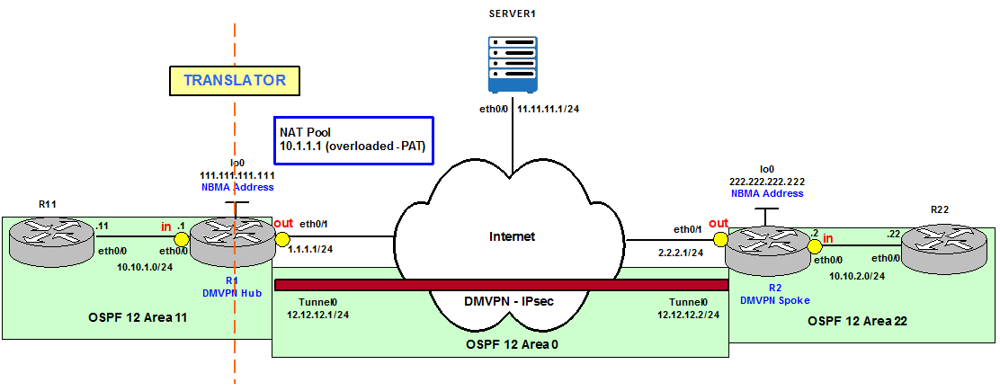
Figure 5
R1 and R2 instead of defining a NAT Pool in this example, they have been configured to use Port Address Translation (PAT). This means they are using their eth0/1 IP address (outside NAT interface) and Port information to do NAT. In addition the Access List (ACL) ANY_SOURCE defines what Inside local traffic is going to be translated (any traffic going to any destination in the configuration below).
interface Ethernet0/0
ip nat inside
interface Ethernet0/1
ip nat outside
ip nat inside
interface Ethernet0/1
ip nat outside
ip access-list extended ANY_SOURCE
permit ip any any
ip nat inside source list ANY_SOURCE interface Ethernet0/1 overload
Ping to Server1
Once NAT is configured on R1 and R2, R11 pings Server 1. This is shown in Figure 6.
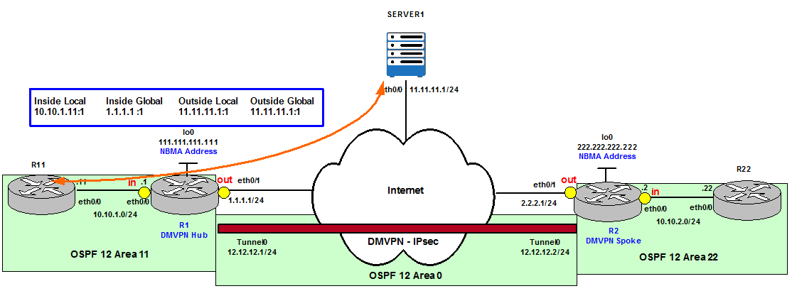
Figure 6
R11#ping 11.11.11.1
Type escape sequence to abort.
Sending 5, 100-byte ICMP Echos to 11.11.11.1, timeout is 2 seconds:
!!!!!
Success rate is 100 percent (5/5), round-trip min/avg/max = 1/1/3 ms
Type escape sequence to abort.
Sending 5, 100-byte ICMP Echos to 11.11.11.1, timeout is 2 seconds:
!!!!!
Success rate is 100 percent (5/5), round-trip min/avg/max = 1/1/3 ms
We verify that R1 translates the source, Inside local, to Inside global and is using port information.
R1#show ip nat translations
Pro Inside global Inside local Outside local Outside global
icmp 1.1.1.1:1 10.10.1.11:1 11.11.11.1:1 11.11.11.1:1
Pro Inside global Inside local Outside local Outside global
icmp 1.1.1.1:1 10.10.1.11:1 11.11.11.1:1 11.11.11.1:1
DMVPN establishment failure
However, we can see R1 and R2 are getting some syslog messages saying that IPsec negotiation cannot be completed.
R1#
*Dec 19 14:14:12.474: %CRYPTO-4-RECVD_PKT_INV_SPI: decaps: rec’d IPSEC packet has invalid spi for destaddr=111.111.111.111, prot=50, spi=0x312A9DA4(824876452), srcaddr=2.2.2.1, input interface=Ethernet0/1
*Dec 19 14:14:12.474: %CRYPTO-4-RECVD_PKT_INV_SPI: decaps: rec’d IPSEC packet has invalid spi for destaddr=111.111.111.111, prot=50, spi=0x312A9DA4(824876452), srcaddr=2.2.2.1, input interface=Ethernet0/1
R2#
*Dec 19 14:14:42.290: %CRYPTO-4-RECVD_PKT_INV_SPI: decaps: rec’d IPSEC packet has invalid spi for destaddr=222.222.222.222, prot=50, spi=0x53B46A52(1404332626), srcaddr=1.1.1.1, input interface=Ethernet0/1
R2#
*Dec 19 14:18:47.381: %CRYPTO-4-IKMP_NO_SA: IKE message from 1.1.1.1 has no SA and is not an initialization offer
R2, the DMVPN Spoke who triggers the DMPVN and implicitly the IPsec negotiation, shows the Crypto Security Association (SA) as MM_NO_STATE instead of QM_IDLE and the DMVPN State as IKE instead of UP. This means there is a problem with Crypto negotiation between the endpoints (R1 and R2).
R2#show dmvpn
Legend: Attrb –> S – Static, D – Dynamic, I – Incomplete
N – NATed, L – Local, X – No Socket
T1 – Route Installed, T2 – Nexthop-override
C – CTS Capable
# Ent –> Number of NHRP entries with same NBMA peer
NHS Status: E –> Expecting Replies, R –> Responding, W –> Waiting
UpDn Time –> Up or Down Time for a Tunnel
==========================================================================
Interface: Tunnel0, IPv4 NHRP Details
Type:Spoke, NHRP Peers:1,
# Ent Peer NBMA Addr Peer Tunnel Add State UpDn Tm Attrb
—– ————— ————— —– ——– —–
1 111.111.111.111 12.12.12.1 IKE 00:01:58 S
R2#show crypto isakmp sa
IPv4 Crypto ISAKMP SA
dst src state conn-id status
111.111.111.111 222.222.222.222 MM_NO_STATE 0 ACTIVE
R22#traceroute 10.10.1.11
Type escape sequence to abort.
Tracing the route to 10.10.1.11
VRF info: (vrf in name/id, vrf out name/id)
1 * * *
2 * * *
3 * * *
[…]
Type escape sequence to abort.
Tracing the route to 10.10.1.11
VRF info: (vrf in name/id, vrf out name/id)
1 * * *
2 * * *
3 * * *
[…]
The translation rule defined (ip nat inside source list ANY_SOURCE interface Ethernet0/1 overload) is a dynamic NAT rule (static keyword is not configured) which means that traffic that has not been originated from the Inside to begin with it is going to be blocked from the Outside. Only returning packets with translated sources are allowed.
In our example R2 is the DMVPN Spoke and is who is going to trigger the IPsec/DMVPN negotiation with R1. R1 is the DMVPN Hub and only listens to incoming requests in order to form the encrypted tunnel. The problem here is there is no a translation entry in R1’s NAT table for this traffic originated from the Inside therefore the IPsec negotiation originated from R2 is going to be blocked.
It is a security measure because if everything is being translated, this means the packets dropped are unsolicited packets. In this example this is not only affecting the data plane, it is also affecting the control plane.
The solution is to bypass NAT for Crypto Protocols (isakmp and IPSec ESP). It is necessary to be more specific when we define the ACL to allow the crypto negotiation to happen and then the DMVPN establishment.
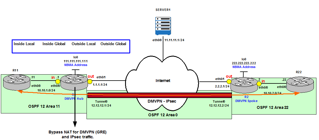
Figure 7
Bypass NAT for any Crypto negotiation traffic means when R2 (222.222.222.222) presents its isakmp and IPsec proposals to R1 (111.111.111.111) R1 does not check its Translation database because this traffic is exempted from NAT. As long as peer addresses (111.111.111.111 and 222.222.222.222) are reachable the negotiation happens as normal. In our topology the peer addresses are reachable via BGP.
R1#show ip route 222.222.222.222
Routing entry for 222.222.222.222/32
Known via “bgp 65001”, distance 20, metric 0
Tag 65002, type external
Last update from 2.2.2.1 00:02:54 ago
Routing Descriptor Blocks:
* 2.2.2.1, from 2.2.2.1, 00:02:54 ago
Route metric is 0, traffic share count is 1
AS Hops 1
Route tag 65002
MPLS label: none
Routing entry for 222.222.222.222/32
Known via “bgp 65001”, distance 20, metric 0
Tag 65002, type external
Last update from 2.2.2.1 00:02:54 ago
Routing Descriptor Blocks:
* 2.2.2.1, from 2.2.2.1, 00:02:54 ago
Route metric is 0, traffic share count is 1
AS Hops 1
Route tag 65002
MPLS label: none
R2#show ip route 111.111.111.111
Routing entry for 111.111.111.111/32
Known via “bgp 65002”, distance 20, metric 0
Tag 65001, type external
Last update from 1.1.1.1 00:03:02 ago
Routing Descriptor Blocks:
* 1.1.1.1, from 1.1.1.1, 00:03:02 ago
Route metric is 0, traffic share count is 1
AS Hops 1
Route tag 65001
MPLS label: none
Routing entry for 111.111.111.111/32
Known via “bgp 65002”, distance 20, metric 0
Tag 65001, type external
Last update from 1.1.1.1 00:03:02 ago
Routing Descriptor Blocks:
* 1.1.1.1, from 1.1.1.1, 00:03:02 ago
Route metric is 0, traffic share count is 1
AS Hops 1
Route tag 65001
MPLS label: none
Therefore, this configuration on R1/R2 does not mean filter the traffic (deny), it means do not perform translation and route as normal (as NAT was never configured).
no ip access-list extended ANY_SOURCE
ip access-list extended ANY_SOURCE
deny udp any any eq isakmp
deny udp any any eq non500-isakmp
deny esp any any
permit ip any any
ip access-list extended ANY_SOURCE
deny udp any any eq isakmp
deny udp any any eq non500-isakmp
deny esp any any
permit ip any any
R2(config-if)#do show dmvpn
Legend: Attrb –> S – Static, D – Dynamic, I – Incomplete
N – NATed, L – Local, X – No Socket
T1 – Route Installed, T2 – Nexthop-override
C – CTS Capable
# Ent –> Number of NHRP entries with same NBMA peer
NHS Status: E –> Expecting Replies, R –> Responding, W –> Waiting
UpDn Time –> Up or Down Time for a Tunnel
==========================================================================
Interface: Tunnel0, IPv4 NHRP Details
Type:Spoke, NHRP Peers:1,
# Ent Peer NBMA Addr Peer Tunnel Add State UpDn Tm Attrb
—– ————— ————— —– ——– —–
1 111.111.111.111 12.12.12.1 UP 00:01:18
R2#show ip nat translations
R22#traceroute 10.10.1.11
Type escape sequence to abort.
Tracing the route to 10.10.1.11
VRF info: (vrf in name/id, vrf out name/id)
1 10.10.2.2 1 msec 0 msec 1 msec
2 12.12.12.1 2 msec 8 msec 4 msec
3 10.10.1.11 9 msec 5 msec *
Type escape sequence to abort.
Tracing the route to 10.10.1.11
VRF info: (vrf in name/id, vrf out name/id)
1 10.10.2.2 1 msec 0 msec 1 msec
2 12.12.12.1 2 msec 8 msec 4 msec
3 10.10.1.11 9 msec 5 msec *
For more information about DMPVN configuration check Dynamic Multipoint VPN (DMVPN) and IGP Routing Protocols.
For more information about Crypto configuration (isakmp and IPsec) check IPsec: Crypto Maps, GRE and VTI.
Scenario 2 – Basic Static NAT Translation
The difference between Static and Dynamic NAT is Static NAT is reversible; it allows Inside to Outside but also Outside to Inside translation. Dynamic NAT, however, only allows Inside to Outside and the return translation as we saw in our previous example.
This configuration is useful when we want to allow access to Internal Public Services such as Email or Web Applications.
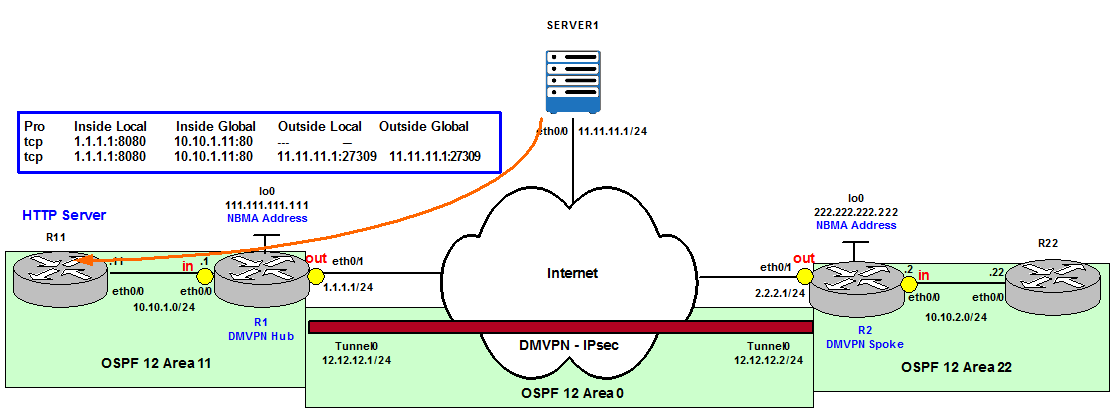
Figure 8
We configure R11 as HTTP Server.
R11(config)#ip http server
Now we configure on R1 a static NAT translation that allows external TCP connections to R1’s eth0/1 IP Address 1.1.1.1 on Port 8080 to be forwarded to R11’s eth0/0 IP address 10.10.1.11 on Port 80. Notice that the ports do not have to be equal, which can help to hide the real ports used for security reasons (bypass port scanners on well known ports such as HTTP – TCP 80).
R1(config)# ip nat inside source static tcp 10.10.1.11 80 1.1.1.1 8080
R1#show ip nat translations
Pro Inside global Inside local Outside local Outside global
tcp 1.1.1.1:8080 10.10.1.11:80 — —
SERVER1#telnet 1.1.1.1 8080
Trying 1.1.1.1, 8080 … Open
get
HTTP/1.1 400 Bad Request
Date: Wed, 20 Dec 2017 20:03:04 GMT
Server: cisco-IOS
Accept-Ranges: none400 Bad Request
[Connection to 1.1.1.1 closed by foreign host]
Trying 1.1.1.1, 8080 … Open
get
HTTP/1.1 400 Bad Request
Date: Wed, 20 Dec 2017 20:03:04 GMT
Server: cisco-IOS
Accept-Ranges: none400 Bad Request
[Connection to 1.1.1.1 closed by foreign host]
We can see the new entry in the Translation table.
R1#show ip nat translations
Pro Inside global Inside local Outside local Outside global
tcp 1.1.1.1:8080 10.10.1.11:80 11.11.11.1:27309 11.11.11.1:27309
tcp 1.1.1.1:8080 10.10.1.11:80 — —
Pro Inside global Inside local Outside local Outside global
tcp 1.1.1.1:8080 10.10.1.11:80 11.11.11.1:27309 11.11.11.1:27309
tcp 1.1.1.1:8080 10.10.1.11:80 — —
Scenario 3 – Server TCP Load Balancing
It is possible to Load Balance (Round Robin method) using NAT incoming connections to a pool of servers in the Inside network.
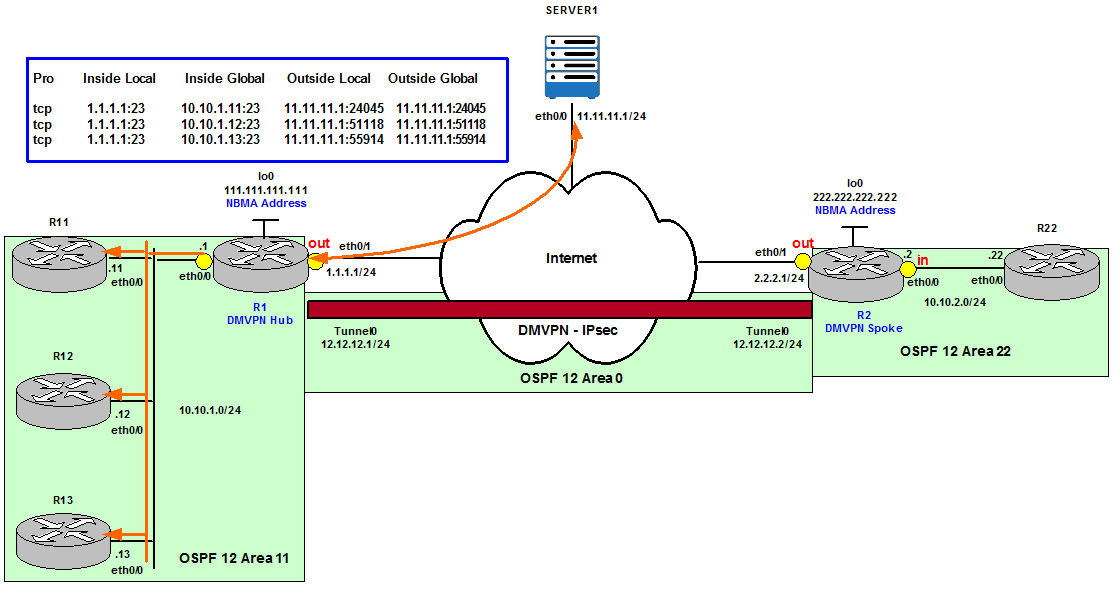
Figure 9
Allocation is done on a round-robin basis and only when a new connection is opened from the Outside to the Inside network. Non-TCP traffic is passed untranslated (unless other translations are configured).
A rotary pool of sequential IP addresses is defined as a NAT Pool of Internal Servers. Then Destination addresses that match the access list INSIDE_GLOBAL are replaced with addresses from the rotary pool.
R1 Configuration:
ip nat pool INTERNAL_SERVERS 10.10.1.11 10.10.1.13 prefix-length 24 type rotary
ip access-list standard INSIDE_GLOBAL
permit 1.1.1.1
ip nat inside destination list INSIDE_GLOBAL pool INTERNAL_SERVERS
ip access-list standard INSIDE_GLOBAL
permit 1.1.1.1
ip nat inside destination list INSIDE_GLOBAL pool INTERNAL_SERVERS
To verify the configuration we telnet from Server1 to R1’s Inside Global IP address several times. We can see every time we telnet we connect to a different Internal router.
SERVER1#telnet 1.1.1.1
Trying 1.1.1.1 … Open
User Access Verification
Password:
R12>exit
[Connection to 1.1.1.1 closed by foreign host]
Trying 1.1.1.1 … Open
User Access Verification
Password:
R12>exit
[Connection to 1.1.1.1 closed by foreign host]
SERVER1#telnet 1.1.1.1
Trying 1.1.1.1 … Open
User Access Verification
Password:
R13>exit
[Connection to 1.1.1.1 closed by foreign host]
SERVER1#telnet 1.1.1.1
Trying 1.1.1.1 … Open
User Access Verification
Password:
R11>exit
[Connection to 1.1.1.1 closed by foreign host]
R1#show ip nat translations
Pro Inside global Inside local Outside local Outside global
tcp 1.1.1.1:23 10.10.1.11:23 11.11.11.1:24045 11.11.11.1:24045
tcp 1.1.1.1:23 10.10.1.12:23 11.11.11.1:51118 11.11.11.1:51118
tcp 1.1.1.1:23 10.10.1.13:23 11.11.11.1:55914 11.11.11.1:55914
Pro Inside global Inside local Outside local Outside global
tcp 1.1.1.1:23 10.10.1.11:23 11.11.11.1:24045 11.11.11.1:24045
tcp 1.1.1.1:23 10.10.1.12:23 11.11.11.1:51118 11.11.11.1:51118
tcp 1.1.1.1:23 10.10.1.13:23 11.11.11.1:55914 11.11.11.1:55914
Scenario 4 – Route-map Reversible
There is a common misunderstanding of using the reversible option for NAT with route-maps configuration. A priori it seems to be the solution to be able to initiate a connection from the Outside to the Inside Global dynamically. However, as we will see, we still need the connection to be originated from the Inside first in order to accept future connections originated from the Outside.
On R1 we configure that traffic originated from R11’s eth0/0 IP address to Server1 is going to be translated to an Inside Global IP address from the pool 1.1.1.10 – 1.1.1.20.
ip access-list extended R11_TO_SERVER1
permit ip host 10.10.1.11 host 11.11.11.1
route-map R11_TO_SERVER1_MAP permit 10
match ip address R11_TO_SERVER1
permit ip host 10.10.1.11 host 11.11.11.1
route-map R11_TO_SERVER1_MAP permit 10
match ip address R11_TO_SERVER1
ip nat pool INSIDE_GLOBAL 1.1.1.10 1.1.1.20 prefix-length 24
ip nat inside source route-map R11_TO_SERVER1_MAP pool INSIDE_GLOBAL
We verify our configuration with a Ping from R11 to Server1 (11.11.11.1) and we check the translation has occurred.
Verification:
R11#ping 11.11.11.1
Type escape sequence to abort.
Sending 5, 100-byte ICMP Echos to 11.11.11.1, timeout is 2 seconds:
!!!!!
Success rate is 100 percent (5/5), round-trip min/avg/max = 2/2/3 ms
Type escape sequence to abort.
Sending 5, 100-byte ICMP Echos to 11.11.11.1, timeout is 2 seconds:
!!!!!
Success rate is 100 percent (5/5), round-trip min/avg/max = 2/2/3 ms
Note that only a particular entry for the flow of Ping packets was created here. This happens for all flows initiated from Inside. The entry would be so specific on the transport protocol, addresses and ports that it would be impossible to initiate a new flow from Outside and have it delivered to the Inside device because it would not match any entry in the NAT translation table.
R1#show ip nat translations
Pro Inside global Inside local Outside local Outside global
icmp 1.1.1.10:0 10.10.1.11:0 11.11.11.1:0 11.11.11.1:0
Pro Inside global Inside local Outside local Outside global
icmp 1.1.1.10:0 10.10.1.11:0 11.11.11.1:0 11.11.11.1:0
Now let’s add the reversible keyword and see what happens.

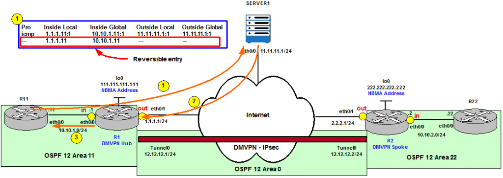
Figure 10
R1#clear ip nat translation *
R1(config)# ip nat inside source route-map R11_TO_SERVER1_MAP pool INSIDE_GLOBAL reversible
R1(config)# ip nat inside source route-map R11_TO_SERVER1_MAP pool INSIDE_GLOBAL reversible
Now we Ping from Outside, Server1, to the Inside Global IP address 1.1.1.11 (the next available IP address from the INSIDE_GLOBAL pool). We can see this traffic is being blocked, therefore even with reversible option configured, traffic from the Outside to the Inside is not allowed.
SERVER1#ping 1.1.1.11
Type escape sequence to abort.
Sending 5, 100-byte ICMP Echos to 1.1.1.10, timeout is 2 seconds:
…..
Success rate is 0 percent (0/5)
Type escape sequence to abort.
Sending 5, 100-byte ICMP Echos to 1.1.1.10, timeout is 2 seconds:
…..
Success rate is 0 percent (0/5)
We now initiate the Ping from R11 instead. We can see in the output below that the Ping is successful.
R11#ping 11.11.11.1
Type escape sequence to abort.
Sending 5, 100-byte ICMP Echos to 11.11.11.1, timeout is 2 seconds:
!!!!!
Success rate is 100 percent (5/5), round-trip min/avg/max = 1/1/4 ms
Type escape sequence to abort.
Sending 5, 100-byte ICMP Echos to 11.11.11.1, timeout is 2 seconds:
!!!!!
Success rate is 100 percent (5/5), round-trip min/avg/max = 1/1/4 ms
If we check the NAT table we note that there are now two entries. The first one is specific to the flow, however, the second entry simply puts the Inside local and the Inside global addresses into mutual correspondence. Now, if somebody from Outside initiates a connection to the address 1.1.1.11 (the Inside global in this case), it will be translated back to 10.10.1.11 thanks to this “template” entry that is not specific to any flow, just to the two corresponding addresses.
R1(config)#do show ip nat translations
Pro Inside global Inside local Outside local Outside global
icmp 1.1.1.11:1 10.10.1.11:1 11.11.11.1:1 11.11.11.1:1
— 1.1.1.11 10.10.1.11 — —
Pro Inside global Inside local Outside local Outside global
icmp 1.1.1.11:1 10.10.1.11:1 11.11.11.1:1 11.11.11.1:1
— 1.1.1.11 10.10.1.11 — —
Moreover, this entry does not expire. After a while if we show the translations we can see this entry is still there whereas the more specific has expired.
R1#show ip nat translations
Pro Inside global Inside local Outside local Outside global
— 1.1.1.11 10.10.1.11 — —
Pro Inside global Inside local Outside local Outside global
— 1.1.1.11 10.10.1.11 — —
So after the first packet went from Inside to Outside, the router with the reversible keyword (R1 in our topology) created a mapping and entered this template entry into the NAT translation table so that for the future, a traffic from Outside can come in and be forwarded to the Inside device. This traffic does not need to be the same traffic that was originated from the Inside (a Ping in our example), it could be any traffic (for example a Telnet).
SERVER1#telnet 1.1.1.11
Trying 1.1.1.11 … Open
User Access Verification
Password:
R11>
Trying 1.1.1.11 … Open
User Access Verification
Password:
R11>
Scenario 5 – Static Policy NAT
Static policy NAT (static NAT with route-maps) allows the use of mappings to different Inside global IP addresses for the same Inside local IP address. The route-maps are used to classify what traffic is used with what NAT translation rule. This configuration is commonly used on multi-homed routers out to multiple Internet Service Providers (ISPs).
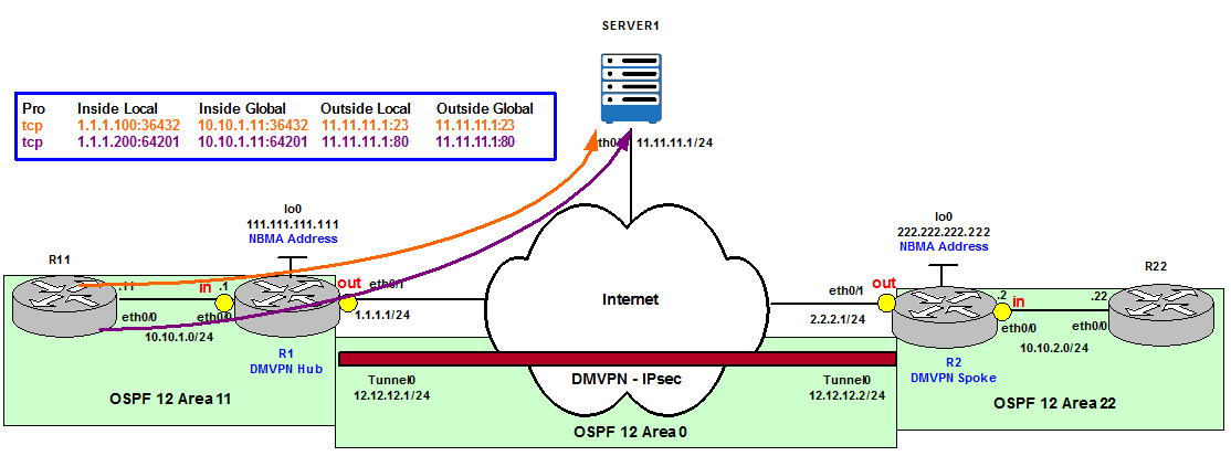
Figure 11
In our example, we want to use different Outside global IP addresses depending on the type of traffic, Telnet or HTTP, that is originated from Server1 and going to R11.
This is R1 Configuration:
ip access-list extended R11_TO_SERVER1_HTTP
permit tcp host 10.10.1.11 host 11.11.11.1 eq www
ip access-list extended R11_TO_SERVER1_TELNET
permit tcp host 10.10.1.11 host 11.11.11.1 eq telnet
permit tcp host 10.10.1.11 host 11.11.11.1 eq www
ip access-list extended R11_TO_SERVER1_TELNET
permit tcp host 10.10.1.11 host 11.11.11.1 eq telnet
route-map R11_TO_SERVER1_TELNET_MAP permit 10
match ip address R11_TO_SERVER1_TELNET
route-map R11_TO_SERVER1_HTTP_MAP permit 10
match ip address R11_TO_SERVER1_HTTP
ip nat inside source static 10.10.1.11 1.1.1.100 route-map R11_TO_SERVER1_TELNET_MAP
ip nat inside source static 10.10.1.11 1.1.1.200 route-map R11_TO_SERVER1_HTTP_MAP
The output below verifies the Inside global IP address used is different depending on the traffic.
R1#show ip nat translations
Pro Inside global Inside local Outside local Outside global
— 1.1.1.100 10.10.1.11 — —
— 1.1.1.200 10.10.1.11 — —
Pro Inside global Inside local Outside local Outside global
— 1.1.1.100 10.10.1.11 — —
— 1.1.1.200 10.10.1.11 — —
R11#telnet 11.11.11.1
Trying 11.11.11.1 … Open
User Access Verification
Password:
SERVER1>
Trying 11.11.11.1 … Open
User Access Verification
Password:
SERVER1>
R1#show ip nat translations
Pro Inside global Inside local Outside local Outside global
tcp 1.1.1.100:36432 10.10.1.11:36432 11.11.11.1:23 11.11.11.1:23
— 1.1.1.100 10.10.1.11 — —
— 1.1.1.200 10.10.1.11 — —
Pro Inside global Inside local Outside local Outside global
tcp 1.1.1.100:36432 10.10.1.11:36432 11.11.11.1:23 11.11.11.1:23
— 1.1.1.100 10.10.1.11 — —
— 1.1.1.200 10.10.1.11 — —
R11#telnet 11.11.11.1 80
Trying 11.11.11.1, 80 … Open
get
HTTP/1.1 400 Bad Request
Date: Thu, 21 Dec 2017 10:46:53 GMT
Server: cisco-IOS
Accept-Ranges: none
400 Bad Request
[Connection to 11.11.11.1 closed by foreign host]
Trying 11.11.11.1, 80 … Open
get
HTTP/1.1 400 Bad Request
Date: Thu, 21 Dec 2017 10:46:53 GMT
Server: cisco-IOS
Accept-Ranges: none
400 Bad Request
[Connection to 11.11.11.1 closed by foreign host]
R1#show ip nat translations
Pro Inside global Inside local Outside local Outside global
tcp 1.1.1.100:36432 10.10.1.11:36432 11.11.11.1:23 11.11.11.1:23
tcp 1.1.1.200:64201 10.10.1.11:64201 11.11.11.1:80 11.11.11.1:80
— 1.1.1.100 10.10.1.11 — —
— 1.1.1.200 10.10.1.11 — —
Pro Inside global Inside local Outside local Outside global
tcp 1.1.1.100:36432 10.10.1.11:36432 11.11.11.1:23 11.11.11.1:23
tcp 1.1.1.200:64201 10.10.1.11:64201 11.11.11.1:80 11.11.11.1:80
— 1.1.1.100 10.10.1.11 — —
— 1.1.1.200 10.10.1.11 — —
Scenario 6 – Outside NAT and add-route
Outside NAT translates the source address of the IP packets that travel from Outside of the network to Inside the network. This action translates the destination address of the IP packets that travel in the opposite direction, from Inside to Outside the network. This command is useful in situations such as overlapping networks, where the Inside network addresses overlap addresses that are Outside the network.
Figure 12 shows the NAT translation process in 4 steps when Outside NAT is configured on R1.
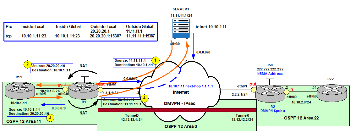
Figure 12
R1 configuration:
ip access-list standard SERVER1
permit 11.11.11.1
ip nat pool NAT_POOL 20.20.20.1 20.20.20.10 netmask 255.255.255.0
ip nat outside source list SERVER1 pool NAT_POOL
permit 11.11.11.1
ip nat pool NAT_POOL 20.20.20.1 20.20.20.10 netmask 255.255.255.0
ip nat outside source list SERVER1 pool NAT_POOL
When Server1 (11.11.11.1) does a Telnet to R11’s eth0/0 IP address (10.10.1.11 – Inside local IP address), R1 checks its NAT pool and chooses the first IP available (20.20.20.1). R1 changes the source of the packet to this IP address and forwards it to R11. R11 replies to 20.20.20.1 and the packet is received by R1. R1 translates it to 11.11.11.1 according to the Translation table and forwards the packet to Server1.
SERVER1#telnet 10.10.1.11
Trying 10.10.1.11 … Open
User Access Verification
Password:
R11>exit
Trying 10.10.1.11 … Open
User Access Verification
Password:
R11>exit
R1#show ip nat translations
Pro Inside global Inside local Outside local Outside global
— — — 20.20.20.1 11.11.11.1
tcp 10.10.1.11:23 10.10.1.11:23 20.20.20.1:15387 11.11.11.1:15387
Pro Inside global Inside local Outside local Outside global
— — — 20.20.20.1 11.11.11.1
tcp 10.10.1.11:23 10.10.1.11:23 20.20.20.1:15387 11.11.11.1:15387
R11#show users
Line User Host(s) Idle Location
* 0 con 0 idle 00:00:00
2 vty 0 idle 00:00:02 20.20.20.1
Line User Host(s) Idle Location
* 0 con 0 idle 00:00:00
2 vty 0 idle 00:00:02 20.20.20.1
However, as we mentioned before when R1 does the NAT from Inside to Outside remember that R1 does routing first and once the output interface is selected as part of the routing decision checks if NAT is configured. NAT is configured on R1’s eth0/1 so R1 checks its Translation table and changes the destination of the packet to 11.11.11.1.
Everything works fine because R1 has a default route.
R1#show ip cef 20.20.20.1
0.0.0.0/0
nexthop 1.1.1.2 Ethernet0/1
0.0.0.0/0
nexthop 1.1.1.2 Ethernet0/1
What would happen if we remove the static default route and we define a more specific route to reach Server1?
R1(config)#no ip route 0.0.0.0 0.0.0.0 1.1.1.2
R1(config)#ip route 11.11.11.0 255.255.255.0 1.1.1.2
R1(config)#ip route 11.11.11.0 255.255.255.0 1.1.1.2
Now when R1 tries to route traffic to 20.20.20.1 sees there is no route to the destination.
R1#show ip cef 20.20.20.1
0.0.0.0/0
no route
0.0.0.0/0
no route
R1 does not have a route to 20.20.20.1 or default route anymore so the retuning traffic is dropped and the Telnet does not work.
SERVER1#telnet 10.10.1.11
Trying 10.10.1.11 …
% Connection timed out; remote host not responding
Trying 10.10.1.11 …
% Connection timed out; remote host not responding
This is what the add-route option tries to solve. It adds a route to the Outside local destination. It is a /32 route used for routing and translating packets that travel from Inside to Outside the network.
R1(config)#ip nat outside source list SERVER1 pool NAT_POOL add-route
We verify the result:
SERVER1#telnet 10.10.1.11
Trying 10.10.1.11 … Open
User Access Verification
Password:
R11>
Trying 10.10.1.11 … Open
User Access Verification
Password:
R11>
The output shows a /32 route for the Outside Local address 20.20.20.1, which is created due to the add-route option of the ip nat outside source command.
R1#show ip route
Codes: L – local, C – connected, S – static, R – RIP, M – mobile, B – BGP
D – EIGRP, EX – EIGRP external, O – OSPF, IA – OSPF inter area
N1 – OSPF NSSA external type 1, N2 – OSPF NSSA external type 2
E1 – OSPF external type 1, E2 – OSPF external type 2
i – IS-IS, su – IS-IS summary, L1 – IS-IS level-1, L2 – IS-IS level-2
ia – IS-IS inter area, * – candidate default, U – per-user static route
o – ODR, P – periodic downloaded static route, H – NHRP, l – LISP
a – application route
+ – replicated route, % – next hop override
Gateway of last resort is not set
1.0.0.0/8 is variably subnetted, 2 subnets, 2 masks
C 1.1.1.0/24 is directly connected, Ethernet0/1
L 1.1.1.1/32 is directly connected, Ethernet0/1
10.0.0.0/8 is variably subnetted, 2 subnets, 2 masks
C 10.10.1.0/24 is directly connected, Ethernet0/0
L 10.10.1.1/32 is directly connected, Ethernet0/0
11.0.0.0/24 is subnetted, 1 subnets
S 11.11.11.0 [1/0] via 1.1.1.2
12.0.0.0/8 is variably subnetted, 2 subnets, 2 masks
C 12.12.12.0/24 is directly connected, Tunnel0
L 12.12.12.1/32 is directly connected, Tunnel0
20.0.0.0/32 is subnetted, 1 subnets
S 20.20.20.1 [1/0] via 11.11.11.1
111.0.0.0/32 is subnetted, 1 subnets
C 111.111.111.111 is directly connected, Loopback0
Scenario 7 – Static Extendable NAT and IP Aliasing
To allow static NAT mappings of one Inside local address to multiple Inside global addresses, the keyword extendable is added to the end of the mapping statements.
The configuration below is not allowed by default.
R1(config)#ip nat inside source static 10.10.1.11 1.1.1.20
R1(config)#ip nat inside source static 10.10.1.11 1.1.1.21
% 10.10.1.11 already mapped (10.10.1.11 -> 1.1.1.20)
R1(config)#ip nat inside source static 10.10.1.11 1.1.1.21
% 10.10.1.11 already mapped (10.10.1.11 -> 1.1.1.20)
We need to add the extendable option.
R1(config)#ip nat inside source static 10.10.1.11 1.1.1.20 extendable
R1(config)#ip nat inside source static 10.10.1.11 1.1.1.21 extendable
R1(config)#ip nat inside source static 10.10.1.11 1.1.1.21 extendable
This is the final result:
R1#show ip nat translations
Pro Inside global Inside local Outside local Outside global
— 1.1.1.20 10.10.1.11 — —
— 1.1.1.21 10.10.1.11 — —
Pro Inside global Inside local Outside local Outside global
— 1.1.1.20 10.10.1.11 — —
— 1.1.1.21 10.10.1.11 — —
SERVER1#telnet 1.1.1.20
Trying 1.1.1.20 … Open
User Access Verification
Password:
R11>exit
Trying 1.1.1.20 … Open
User Access Verification
Password:
R11>exit
SERVER1#telnet 1.1.1.21
Trying 1.1.1.21 … Open
User Access Verification
Password:
R11>exit
R1#show ip nat translations
Pro Inside global Inside local Outside local Outside global
tcp 1.1.1.21:23 10.10.1.11:23 11.11.11.1:21857 11.11.11.1:21857
tcp 1.1.1.20:23 10.10.1.11:23 11.11.11.1:55048 11.11.11.1:55048
— 1.1.1.20 10.10.1.11 — —
— 1.1.1.21 10.10.1.11 — —
Pro Inside global Inside local Outside local Outside global
tcp 1.1.1.21:23 10.10.1.11:23 11.11.11.1:21857 11.11.11.1:21857
tcp 1.1.1.20:23 10.10.1.11:23 11.11.11.1:55048 11.11.11.1:55048
— 1.1.1.20 10.10.1.11 — —
— 1.1.1.21 10.10.1.11 — —
In addition, the router doing NAT keeps record of the Outside global IP addresses by default. The purpose of this alias is so that it will respond to ARP requests sent to the router for the Outside global IP address.
R1#show ip aliases
Address Type IP Address Port
Interface 1.1.1.1
Dynamic 1.1.1.20
Dynamic 1.1.1.21
Interface 10.10.1.1
Interface 12.12.12.1
Interface 111.111.111.111
Address Type IP Address Port
Interface 1.1.1.1
Dynamic 1.1.1.20
Dynamic 1.1.1.21
Interface 10.10.1.1
Interface 12.12.12.1
Interface 111.111.111.111
We can disable this behavior with the no-alias option.
R1(config)#ip nat inside source static 10.10.1.11 1.1.1.20 extendable no-alias
R1(config)#ip nat inside source static 10.10.1.11 1.1.1.21 extendable no-alias
R1(config)#ip nat inside source static 10.10.1.11 1.1.1.21 extendable no-alias
R1#show ip aliases
Address Type IP Address Port
Interface 1.1.1.1
Interface 10.10.1.1
Interface 12.12.12.1
Interface 111.111.111.111
References
http://www.ciscopress.com/articles/article.asp?p=25273&seqNum=4
https://www.cisco.com/c/en/us/support/docs/ip/network-address-translation-nat/13770-1.html